Femtet Help/Manual
 

Home / How to Set Analysis Condition / List of Analysis Condition Tabs / Mesh Tab

Mesh Tab

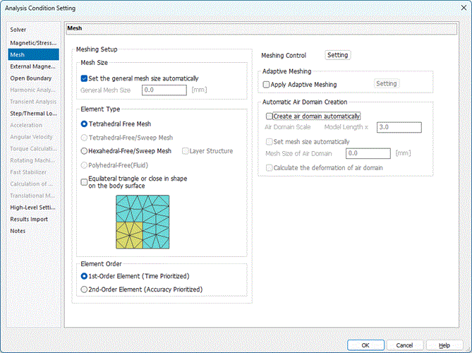
Various meshing conditions are set on this tab.

It is in the [Analysis Condition Setting] dialog box. See also [How to Set Analysis Condition] for detail about the dialog box..


To optimize the simulation accuracy, please see [How to Optimize the Simulation Accuracy].


Setting Items

Notes

Meshing Setup


Set the general mesh size automatically

Sets the general mesh size to one tenth of the maximum model dimension automatically.


General Mesh Size

Applies the general mesh size unless specific mesh size is set for the bodies and topologies,
The general mesh size is used for the edge length of triangle, rectangle (2D), and tetrahedron (3D) in the model.

For the general mesh size, [Variables] can be available as well as number.

See [General Mesh Size] for more information.


Element Type


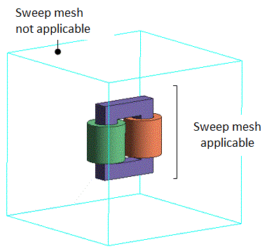
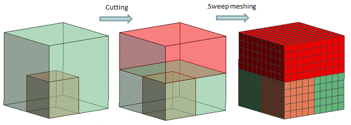
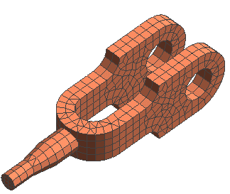
Model for Explanation: Model including bodies that Sweep Mesh can be applied to and bodies that not be applied. The bodies that sweep mesh can be applied to are automatically searched and their sweep directions are automatically determined.
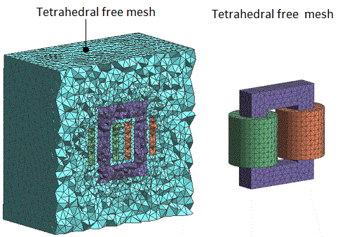
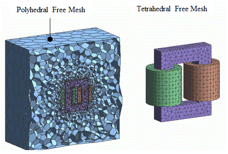
Tetrahedral Free Mesh: Default Setting; All bodies are divided by Tetrahedral Free Mesh.
Tetrahedral Free Mesh/Sweep Mesh:

The bodies that can be swept are divided by sweep mesh and the bodies that cannot are divided by tetrahedral free mesh. This meshing is applicable only for the 3D stress and thermal solvers.
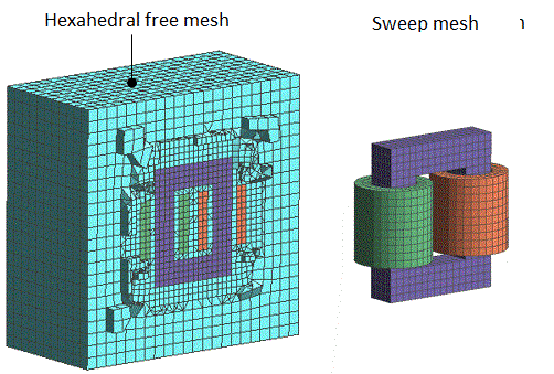
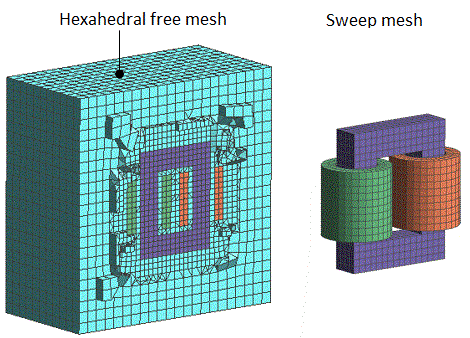
Hexahedral Free Mesh/Sweep Mesh:

The bodies that can be swept are divided by sweep mesh and the bodies that cannot are divided by Hexahedral Free Mesh.
Layer Structure:

To apply sweep mesh to all bodies, cut the bodies by the plane perpendicular to the vertical direction before creating sweep meshes. An error will occur if bodies that cannot be swept are left.

This meshing is not applicable for the piezoelectric analysis.
 

Polyhedral Free Mesh [Fluid]


Fluid portion can be automatically divided by polyhedral free mesh

Solid portion can be automatically divided by tetrahedral free mesh


Available only for the fluid analysis.

Control Volume Type: Cell-centered Base[speed prioritized]


For the 2D analysis, selectable from triangular and rectangular elements.

For the 3D analysis, selectable from tetrahedral and hexahedral elements.


  • Rectangular and hexahedral elements are not supported in the electromagnetic analysis.

  • Hexahedral element is not supported in the magnetic-transient analysis.

  • Rectangular and hexahedral elements are not supported if the adaptive meshing is applied or Mesher G1 is used.


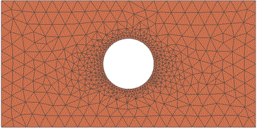
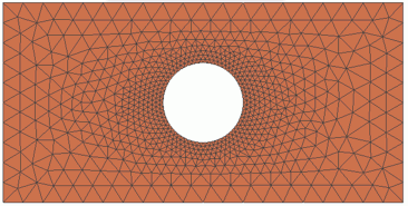
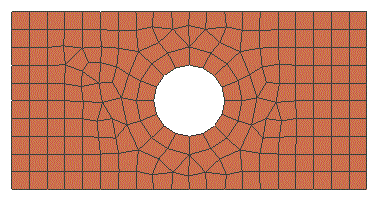
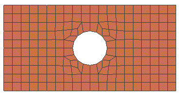
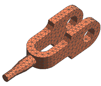
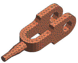
Equilateral Triangle or Close in Shape Mesh on Body Surface

Tries to create the mesh shape as close to equilateral triangle as possible. (Square meshes in the case of rectangular elements)

The shape will not necessarily become equilateral triangle.

In the 3D analysis, the equilateral triangular meshes are created on the body surface only.


Triangular Elements
Triangular Elements ([Equilateral triangle (or close in shape)] is selected)
Rectangular Elements
Rectangular Elements ([Square (or close in shape)] is selected)
Tetrahedral Elements
Tetrahedral Elements ([Equilateral triangle (or close in shape)] is selected, equilateral triangle only on surface)
Hexahedral Elements
Same as the left.


Order of Element

Specifies the order of the element.

The default setting is the 2nd-order element.

Element Type

Features

Suitable Cases for Use

1st-order Element

  • Less accurate than the 2nd-order element.

  • The calculation time is shorter and less memory is required.

  • When the model is complicated and the memory is short for the 2nd-order element.

  • When the shorter calculation time is required.

2nd-Order Element

  • More accurate than the 1st-order element.

  • The calculation time is longer and more memory is required.

  • When the better accuracy is required and the calculation time is within the acceptable length.


  • Not selectable for the magnetic transient analysis (Luvens). Fixed to 1st-order element.

  • Fluid portion in fluid or fluid-thermal analysis is set to be 1st-order element. If 2nd-order element is selected, they will be used for solid portion.

  • In the magnetic harmonic analysis, the 2nd-order element is forcibly applied if the thin meshes are generated by selecting [Generate thin meshes (skin depth) on the conductor surface].
    This is because the accuracy of the 1st-order element is not good enough.


Meshing Control


See [Meshing Control] for the detail.


Adaptive Meshing


Creates fine meshes automatically where the electric fields or mechanical stresses change drastically, and repeats calculations for higher accuracy.

See [Technical Note] for the theoretical details.


Also, see [Adaptive Mesh Setting] for the detailed setting.


Automatic Ambient Air Creation


Sets for creating the ambient air body automatically. It is mainly for the electromagnetic analysis using the finite element method.

It is selectable in the magnetic analysis, electric analysis (other than resistance analysis), and stress analysis.


  • In the coupled analysis, automatically created ambient air will not be simulated in the thermal analysis and stress analysis.
    If [Calculate the deformation of ambient air] is selected, the stress analysis is performed assuming that the air is a soft material.


Create Ambient Air Automatically

Creates a body of ambient air automatically when the meshing is executed.

Depending on the analysis condition, the air body in the following form will be created.


In most cases

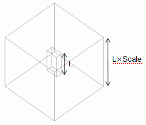
3D analysis: Cube with same length on each edge

2D analysis: Square


Length of edge: Largest length of the original model's X, Y, Z directions times scale of the ambient air

Open Boundary for Outer Boundary Condition

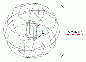
3D analysis: Sphere

2D analysis: Circle


Center: Gravity center of the original model
Radius: Largest radius from the original model times scale of the ambient air


* The origin of the open boundary is automatically set on the center of the sphere or the circle.

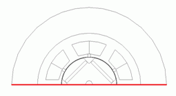
Rotating Machinery (Magnetic Transient Analysis)

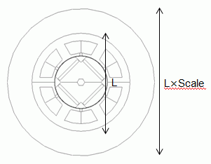
3D analysis: Cylinder

2D analysis: Circle

Radius: Largest radius from the rotation axis of the original model times scale of the ambient air
Thickness of the rotation axis direction: Thickness of the rotation axis direction of the original model times scale of the ambient air


The above forms will be cut at where the following exist.

Plane of symmetry

Air is not needed outside the symmetric plane

Inflow/Outflow face of current (magnetic analysis)

Inflow/outflow face of current needs to be facing the air surface.
Exceptional case is where the following is selected for the direction setting.
[Loop Coil/Magnetic Field Direction], [Specify Inflow/Outflow Faces (In the Air Box)], [Boundary Condition]

2D axisymmetric

Center axis

  • In the case of coupled analysis, the air domain is automatically excluded from the analysis domain in the thermal analysis and stress analysis


Ambient Air Scale

Sets the size of ambient air by scale factor for automatic creation.

Size of the ambient air is determined by the model length multiplied by scale.

Refer to [Size of Ambient Air in Magnetic Analysis] for scale setting.


Set Mesh Size Automatically

If selected, the mesh size of the air domain to be automatically created is automatically determined as follows.

1st-order element: one tenth of the longest part of the ambient air

2nd-order element: one fifth of the longest part of the ambient air


Mesh Size of Air Domain

Sets the mesh size of the ambient air manually.


Calculate the Deformation of Ambient Air

Selectable only in the stress analysis.
Calculate the deformation of the ambient air in the stress analysis. Since the air is assumed to be a soft material, the calculation result will indicate the air is displaced by the deformations of the bodies other than the air.


Frequency-Dependent Meshing

Meshing Setup


The setting method depends on solver.

Electromagnetic Analysis (Hertz)


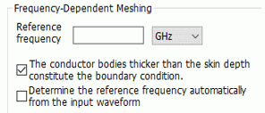
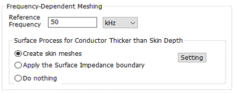
Reference Frequency

Used in the following cases. Set the frequency of your interest.


  1. When the adaptive meshing is used in the harmonic analysis or the transient analysis:
    If [Apply adaptive meshing] is selected in the [Adaptive Meshing Setting] and the reference frequency is specified,
    the adaptive meshing is applied so as to create the optimized meshes at the reference frequency.
    See also [
    Adaptive Mesh Setting].

  2. When the adaptive meshing is used in the waveguide analysis:
    the adaptive meshing is applied so as to create the optimized meshes at the reference frequency.

  3. When [The conductor bodies thicker than the skin depth constitute the boundary condition] is selected:
    The reference frequency is used to calculate the skin depth.
    Also see [The conductor bodies thicker than the skin depth constitute the boundary condition] below.

  4. When [Calculate the Q factor with high accuracy] is selected in the resonant analysis:
    The reference frequency is used to calculate the surface impedance.
    The reference frequency is used to calculate the complex permittivity.

  5. Waveguide frequency analysis:
    The reference frequency is used to calculate the complex permittivity.

  6. Field display of the transient analysis:
    For the current density display, the reference frequency is used to calculate the skin depth of the conductor.


The Conductor Bodies Thicker than the Skin Depth Constitute the Boundary Condition

Sets the surface impedance boundary condition on the conductor body surface which is thicker than the skin depth.
The inside of the body, which is set with surface impedance boundary condition, is excluded from the FEM analysis.
The inside of the conductor is calculated analytically from the electromagnetic field of the conductor surface.

The skin depth is calculated from the reference frequency. See Technical Note [Conductive Body] for the details.


Determine the Reference Frequency Automatically from the Input Waveform

Available for the transient analysis. The reference frequency is automatically determined from the waveform data set in Input Waveform.


Magnetic Analysis (Gauss, Luvens)

Reference Frequency

Used in the following cases. Set the frequency of your interest.

1. Where the adaptive mesh is used in the harmonic analysis.

The meshing is optimized at the specified frequency.

2. Where [Surface Treatment Type for Conductors Thicker Than Skin Depth] is other than [Do nothing].


Surface Process for Conductor Thicker than Skin Depth

Set for the harmonic analysis or transient analysis.

The default setting is [Generate skin meshes].


Surface Process

Note

Recommended Cases

Generate skin meshes

To increase the accuracy, thin meshes are generated on the surface of electrodes if the electrodes are thicker than the skin depth.

Thin meshes are crated at electrode edges

The thickness of thin meshes is the skin depth.

The skin depth is calculated from the reference frequency.


The calculation takes longer than [Apply the surface impedance boundary],

but it can be applicable for most cases.


The number of layers and thickness are set by [Setting] button.


  • If [Automatic] is selected at Matrix Solver Type, [Direct Method] will be selected.

  • For the harmonic analysis, the element type is forcibly set to be 2nd-order automatically.

  • Not applicable if Mesher G1 is used.

The induced current is taken into account for the conductor through which the current is flowing.

For example, bus bars and inductors.

Apply the surface impedance boundary

Applicable for the harmonic analysis.


To increase the accuracy, the impedance boundary is set on the surface of electrodes if the electrodes are thicker than the skin depth.

The skin depth is calculated from the reference frequency.


The calculation is faster than [Generate the skin meshes],

but the application is limited.

Not applicable if both conditions below are set on a conductor.

  • Body attribute > [Current] tab > [Induced Current] > [Yes] is selected

  • The ports are set

When applying, body attribute > [Current] tab > [Induced current] > select [No].


See Technical Note [Conductive Body] for the details.

The induced current is NOT taken into account for the conductor through which the forced current is flowing

For example, induction heating.

Do nothing

No specific setting on the surface of the electrode.

High accuracy is not required for the calculation of induced current or skin depth.


Other Solvers

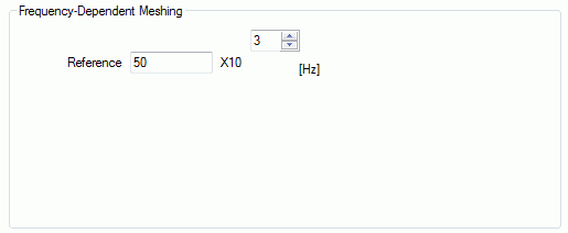
Reference Frequency

Required to be set when the adaptive mesh method is used in the harmonic analysis.

To optimize meshing at the specified frequency, enter the frequency of your interest.