|
Home / Examples / Magnetic Analysis (Luvens, Transient Analysis) / Example 12: Iron Loss by Input Current with Predefined Waveform (Triangle Wave)
Example 12: Iron Loss by Input Current with User-defined Waveform (Triangle Wave)
General
-
The iron loss is calculated when the user-defined waveform current is input to the coil wound on a core. In this example, the waveform is triangle wave.
A square wave can be analyzed in the same way. -
To calculate the iron loss with the user-defined waveform, [Frequency Analysis (FFT)] is used as a calculation method.
-
The core loss, the vectors of the magnetic field and the magnetic flux density are solved.
-
Unless specified in the list below, the default conditions will be applied.
-
Obtain this session's project file. (Right-click and choose 'Save link as')
-
Results will vary depending on Femtet version and the PC environment.
Analysis Space
|
Item |
Settings |
|
Analysis Space |
3D |
|
Model Unit |
mm |
Analysis Conditions
|
Item |
Settings |
|
Solver |
Magnetic Analysis [Luvens] |
|
Analysis Type |
Transient Analysis |
|
Options |
None |
The transient analysis tab is set up as follows.
An analysis is performed for one cycle of a 50 kHz AC input.
To reproduce its waveform well, the timestep is set by dividing the periodic time of 50 kHz by 24.
|
Tab |
Setting Item |
Settings |
|
Transient Analysis |
Timestep |
Automatic |
|
Timestep Setting |
Number of Cycles 1 Select [Change the number of divisions per cycle]. Number of Divisions: 24 |
Model
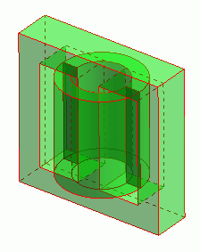
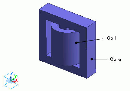
A coil is wound on a core.
The model is defined by the core (Core) and the loop coil (Coil) are defined.
Body Attributes and Materials
|
Body Number/Type |
Body Attribute Name |
Material Name |
|
5/Solid |
Coil |
008_Cu * |
|
6/Solid |
Core |
MB3_23deg_JFE Ferrite * |
* Available from the material DB
The material properties are set up as follows:
[MB3_23deg_JFE Ferrite] is used for the core.
The values for both the B-H curve and iron loss table are taken from the database. The iron loss calculation type is manually changed to [Frequency Analysis (FFT)] from [Amplitude].
For calculation using the iron loss table, the iron loss density is determined based on the amplitude of the magnetic flux density in relation to the specified frequency in the table.
If a sine wave is not used, the harmonic component of the iron loss cannot be taken into account unless the frequency analysis (FFT) is performed.
See Permeability tab for detail.
|
Material Name |
Tab |
Setting |
|
MB3_23deg_JFE Ferrite |
Iron Loss |
Calculation Method: Frequency Analysis (FFT) Fundamental Frequency: Specify frequency/50 [kHz] |
Body attribute is set up as follows to apply current to the loop coil.
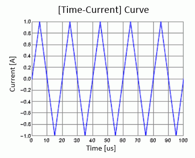
The current is a triangle wave with frequency of 50kHz and amplitude of 1A.
|
Body Attribute Name |
Tab |
Setting |
||||||||||||
|
Coil |
Current |
Waveform: User to Define
[Time-Current] Table
Turns: 100 [Turns] Direction: Loop Coil/Magnetic Field Direction Direction Vector of Magnetic Field: X=0, Y=0, Z=1 |
Enter the values covering one phase in the [Time-Current] table and the current will repeat automatically.
By pressing the graph button of the [Time-Current] table, the repetition can be seen as shown below.
Boundary Conditions
No setting.
Results
To see the iron loss, go to the [Results] tab
and click [Show Numerical Summary Table]  .
.
The results are shown on the [Loss [W] (referring to value over 1 period from the final step)] tab as below.
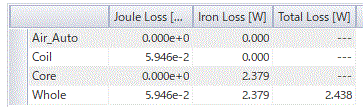
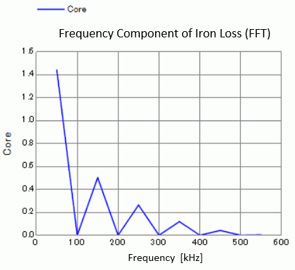
Each frequency component is output on the [Frequency component (FFT) of iron loss [W]] tab.
Below is the results plotted in a graph.
AS the input current is a triangle wave, harmonic components can be seen.
-
See [Loss Calculation in the Magnetic Analysis] for details of the loss.
-
See also [Iron loss calculation].
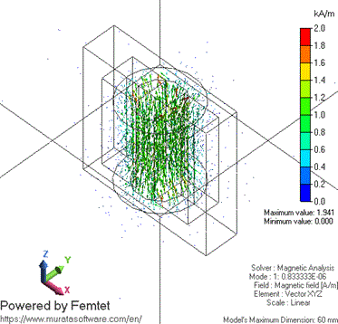
The vectors of the magnetic field at timestep 1 are shown below.
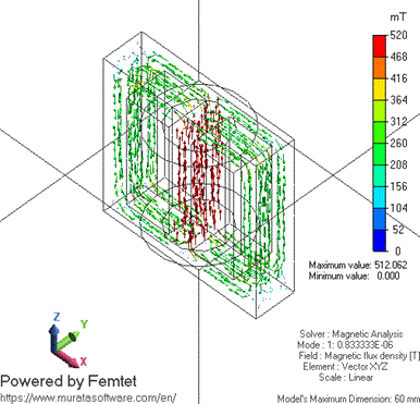
The vectors of the magnetic flux density at timestep 1 are shown below.
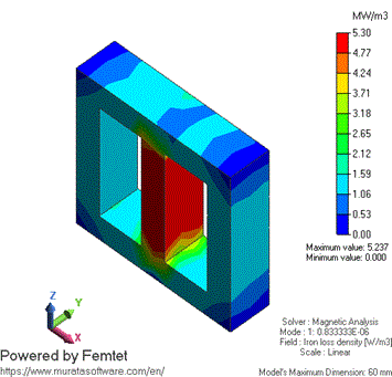
The iron loss density is shown below.