|
Home / Examples / Magnetic Analysis (Luvens, Transient Analysis) / Example 13: Demagnetization of SPM Motor
Example 13: Demagnetization of SPM Motor
General
-
The demagnetization of the SPM motor (surface permanent magnet motor) is analyzed.
-
The torque, the distribution of demagnetization rate, the magnetic flux density, the iron loss, the cogging torque, and the induced voltage are solved.
-
The analysis is coupled with the external circuit.
-
For rotor and stator cores, the homogenizing method is applied to simulate the layer structure of the electromagnetic plates of steel.
-
Unless specified in the list below, the default conditions are applied.
-
Obtain this session's project file. (Right-click and choose 'Save link as')
-
Results will vary depending on Femtet version and the PC environment.
-
In this example, a quarter period symmetric model is used for faster calculation.
Analysis Conditions
|
Item |
Settings |
|
Analysis Space |
2D |
|
Thickness in Depth Direction |
60 [mm] |
|
Unit |
mm |
|
Solver |
Magnetic Analysis [Luvens] |
|
Analysis Type |
Transient Analysis |
|
Analysis Options |
Select External Circuit Coupling. Select Rotating Machinery.
[Partial Model (Symmetric Model) Setting] Select Partial Model. Number of Divisions: 4 [Conversion of External Circuit I/O Values] Select Convert Number of Series: 4 Number of Parallels: 1 Select Convert results to full model for output |
The Rotating Machinery tab is set as follows.
|
Tab |
Setting Item |
Settings |
|
Rotating Machinery |
Rotational Movement |
Select Constant Velocity Number of Rotations: 1800 [r/min] Rotor’s Initial Rotation Position: 0 [deg] |
|
Number of Sliding Mesh Divisions |
Circumferential Division Angle: 1.0 [deg] Rotational Quantity per Step: 1 [mesh] Number of Sliding Mesh Layers: 3 |
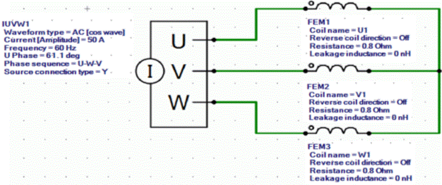
External circuit is as follows.
3-phase AC of 60 Hz and 40 A is applied.
The U phase is calculated with a function to [Search for power phase at the maximum torque].
As [Conversion of external circuit I/O values] is ON, the resistance value of the FEM coil is set to the phase resistance which is equivalent to a full model instead of a quarter model.
See [External Circuit Conversion] and [Example of External Circuit Conversion Setup] for the details of conversion.
Set the Mesh Tab as follows.
|
Tab |
Setting Item |
Settings |
|
Mesh |
Meshing Setup |
Set the general mesh size automatically: Deselect General Mesh Size: 1 [mm] |
|
Automatic Air Domain Creation |
Select Create air domain automatically Air Domain Scale: 1.2 |
The Transient Analysis tab is set up as follows.
The number of calculation steps is 180, circumferential division angle is 1.0 [deg], and rotational quantity per step is 1 [mesh]. The rotation up to 180 degrees (=180*1.0*1) is analyzed.
It can be converted to the electric angle of 360[deg] (=180*4/2) (mechanical angle x number of poles). One period of electric angle is analyzed.
-
As the input power is specified by current, the coil current is in the steady state from the beginning. The torque is also in the steady state.
-
To calculate the iron loss, it is necessary to set the timesteps for one period of electric angle in the steady state, and to define the iron loss characteristic for the material property.
|
Tab |
Setting Item |
Settings |
|||||
|
Transient Analysis |
Timestep |
Automatic |
|||||
|
Table |
|
Model
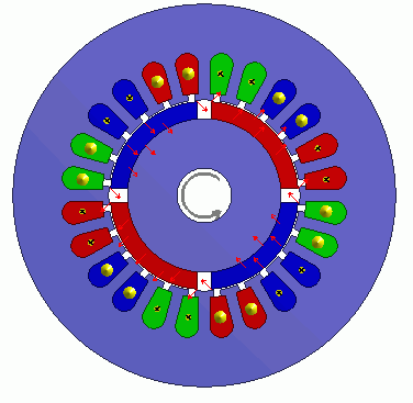
A rotor core and magnet are placed in the center. A stator and coils are placed around them.
The motor has 4 poles and 24 slots.
This is a 2D model analysis.
By utilizing the symmetry, the model is quarter period symmetric.
Rotation period boundary (symmetric) is set.
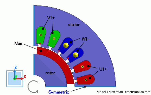
When antiperiodic, the magnetic field is reversed every period. The full model is shown as follows.
|
Body Number/Type |
Body Attribute Name |
Material Name |
|
12/Sheet |
Mag |
R30_50deg_Shin-Etsu Chemical* |
|
11/Sheet |
Rotor |
35JN270_JFE Steel* |
|
28/Sheet |
Stator |
35JN270_JFE Steel* |
|
30/Sheet |
U1+ |
008_Cu * |
|
31/Sheet |
U1+ |
008_Cu * |
|
32/Sheet |
W1- |
008_Cu * |
|
33/Sheet |
W1- |
008_Cu * |
|
34/Sheet |
V1+ |
008_Cu * |
|
35/Sheet |
V1+ |
008_Cu * |
* Available from the material DB
In order to take the irreversible demagnetization into account, the magnet material setting is modified as below.
|
Material Name |
Tab |
Settings |
|
R30_50deg_Shin-Etsu Chemical |
Permeability |
Material Type: Permanent Magnet (Irreversible demagnetization taken into account) |
The body attribute is set up as follows.
For the core, the homogenizing method is selected to simulate the layered steel plates.
|
Body Attribute Name |
Tab |
Settings |
|
Mag |
Direction |
Vector: X=1, Y=0, Z=1 |
|
Current |
Click Yes for induced current setting. |
|
|
Stator/Rotor/Air |
Rotor |
|
|
Rotor |
Layer |
Select Take layer into account Space: 97 [%] Layer Vector: X=0, Y=1, Z=0 |
|
Stator/Rotor/Air |
Rotor |
|
|
Stator |
Layer |
Select Take layer into account Space Factor: 97[%] Layer Vector: X=0, Y=1, Z=0 |
|
Stator/Rotor/Air |
Stator |
|
|
U1+ |
Current |
Waveform: External Circuit Coupling Coil Name on the Circuit: U1 Turns: 35 [Turns] Direction: +Y Direction |
|
Stator/Rotor/Air |
Stator |
|
|
V1+ |
Current |
Waveform: External Circuit Coupling Coil Name on the Circuit: V1 Turns: 35 [Turns] Direction: +Y Direction |
|
Stator/Rotor/Air |
Stator |
|
|
W1- |
Current |
Waveform: External Circuit Coupling Coil Name on the Circuit: W1 Turns: 35 [Turns] Direction: - Y Direction |
|
Stator/Rotor/Air |
Stator |
Boundary Condition
Antiperiodic symmetric boundary (Symmetric) is set.
|
Boundary Condition Name/Topology |
Tab |
Boundary Condition Type |
Settings |
|
Symmetric |
Symmetry/Continuity |
Periodic |
Rotation (Antiperiodic) |
Results
The below are the results.
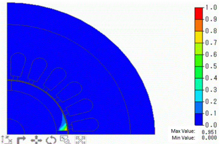
The distribution of the demagnetization rate at the rotation angle of 180 [deg] is shown below.
The right side of the magnet is demagnetized because of the strong demagnetization of the coil.
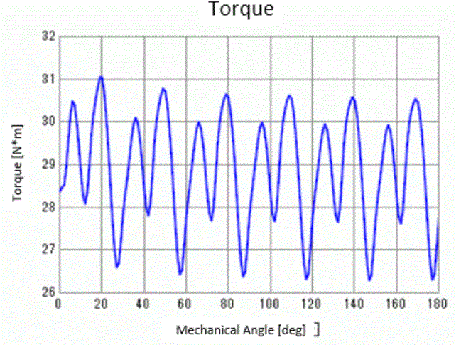
The diagram below shows rotation angle-torque characteristics. It is output to "Torque [N*m]" of the result table.
You can see demagnetization decreases the torque as the rotation goes on.