Femtet Help/Manual
 

Home / How to Set Analysis Condition / List of Analysis Condition Tabs / Motor Characteristics Diagram/Search for Power Phase Tab

Motor Characteristics Diagram/Search for Power Phase Tab

Analysis conditions of the magnetic transient analysis for 3-phase AC motor are set on this tab.

This setting is not necessary unless the calculation is for the characteristics listed below.


  • Search for power phase at the maximum torque
    Searches for a power phase where the motor torque is at its maximum.

  • N-T Characteristics
    Calculates the motor characteristics diagram of the number of rotations and the torque.

  • I-T Characteristics
    Calculates the motor characteristics of the current and the torque.

It is in the [Analysis Condition Setting] dialog box. See also [How to Set Analysis Condition].
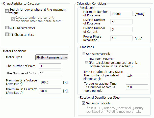


Setting Item

Notes

Characteristics to Calculate


Search for power phase at the maximum torque

Searches for a power phase where the motor torque is at its maximum.

It is faster than sweeping the power phases with parametric analysis.

The motor, which has an external circuit and 3-phase AC power, only can be analyzed.

Please note that the phase setting of the power on the external circuit is ignored.


If Calculate under the current conditions after the phase search is deselected, the power phase only will be output.

If selected, after determining the phase, the calculation will be performed with timesteps, which are set on the transient analysis tab.

The results are all output including the fields.


N-T characteristics

Calculates the motor characteristics diagram of the number of rotations and the torque.

The entire calculation is done with the finite element method.

The motor, which has an external circuit and 3-phase AC power, only can be analyzed.

The Settings Required for the N-T Characteristics Analysis
  • Definition of the model form

  • Definition of the body attribute and material property

  • Definition of the boundary condition

  • Definition of the analysis conditions other than transient analysis tab

  • Definition of the external circuit
    Layout of FEM coils, line connection, and parameter setting
    Layout of 3-Phase AC power and the following parameters
    Waveform type (Note: waveform defined by user is not supported)
    Phase sequence


  • The FEM coils on the external circuit must be 3 (one each for U, V, and W).

  • If more than three FEM coils are needed, set the analysis model as follows.
    If the coils are to be connected in series:
    For the body attribute, go to [Current tab] > [Coil Name on Circuit], and assign the same name to all.
    The resistance of the FEM coils must be set as the sum of coils connected in series.
    If the coils are to be connected in parallel:
    Use period symmetric model that will not require the parallel connection of coils on the external circuit.
    There are no other methods than this to perform analysis.

The Settings Not Required for the N-T Characteristics Analysis (Any Values Acceptable)
  • The number of rotation on the rotating machinery tab

  • Timestep on the transient analysis tab

  • The following parameters for the 3-phase AC power on the external circuit
    Power type (voltage source / current source)
    Voltage/Current value
    Frequency
    Phase of U
    Connection type of the power (Though it does not affect the results, the delta connection tends to take less calculation time.)

Calculation Method

Calculates the power supply voltage and the current amplitude, which will give the maximum torque within the maximum voltage and the maximum current set in the [Motor Conditions]. The calculation is done for each number of rotations.

The iron loss is not taken into account.


I-T characteristics

Calculates the motor characteristics of the current and the torque.

The entire calculation is done with the finite element method.

The motor, which has an external circuit and 3-phase AC power, only can be analyzed.

The Settings Required for the I-T Characteristics Analysis
  • Definition of the model form

  • Definition of the body attribute and material property

  • Definition of the boundary condition

  • Definition of the analysis conditions other than transient analysis tab

  • The number of rotations on the rotating machinery tab

  • Definition of the external circuit
    Layout of FEM coils, line connection, and parameter setting
    Layout of 3-Phase AC power and the following parameters
    Waveform type (Note: waveform defined by user is not supported)
    Phase Sequence

The Settings Not Required for the I-T Characteristics Analysis (Any Values Acceptable)
  • Timestep on the transient analysis tab

  • The following parameters for the 3-phase AC power on the external circuit
    Power type (voltage source / current source)
    Voltage/Current value.
    Frequency (it is automatically calculated from the number of rotations set on the rotating machinery tab and the number of poles)
    Phase of U
    Connection type of the power (Though it does not affect the results, the delta connection tends to take less calculation time.)

Calculation method

Calculates the power supply voltage and the current amplitude, which will give the maximum torque for each current.

The maximum voltage value set in the dialog box is not taken into account.

The iron loss is not taken into account.


Motor Conditions


Motor type

Allows you to select a motor type.

PMSM (Permanent Magnet Synchronous Motor) is only selectable.

IM (Induction Motor) is not supported.


Number of poles

Sets the number of magnetic poles.

Enter the values of the full model. (Even for a partial model such as period symmetric, the values of the full model must be entered. )

It is used to calculate the torque ripple period, which is a reference for averaging time of torque.


Number of slots

Sets the number of slots.

Enter the values of the full model. (Even for a partial model such as period symmetric, the values of the full model must be entered. )

It is used to calculate the torque ripple period, which is a reference for averaging time of torque.


Maximum line voltage (Amplitude)

Sets the maximum value of the line voltage of the power. (It is equivalent to the bus voltage of the inverter.)

It is used to calculate the N-T characteristics.


Specifically, the motor is controlled to keep the voltage below the following values.

  • If the power is Y connection
    Maximum phase voltage = 1/√3*maximum line voltage

  • If the power is delta connection
    Maximum phase voltage = Maximum line voltage


It is not used to calculate the I-T characteristics.


Maximum line current (Amplitude)

Sets the maximum value of line current that is supplied to the motor from the power (inverter).

It is used to calculate the N-T and I-T characteristics.


When calculating the N-T characteristics, the motor is controlled to keep the current below the following values.

  • If the power is Y connection
    Maximum phase current = Maximum line current

  • If the power is delta connection
    Maximum phase current = 1/√3*maximum line current


When calculating the I-T characteristics, it is used as an upper limit of the current value for the calculation points.


Resolution


Sets the resolution for calculations.

The fine resolution will increase the calculation accuracy but it will take more time.


Maximum number of rotations

Sets the maximum number of rotations to calculate for N-T characteristics.


Number of Division of Rotations

Sets the number of divisions of the rotational frequency to calculate for N-T characteristics.


Number of divisions of current

Sets the number of divisions of current to calculate for I-T characteristics.

(Maximum line current (amplitude) is used as an upper limit.)


Power phase resolution

Sets the phase resolution for all calculations when searching for the power phase.


Number of Timesteps


Sets the number of timesteps for calculations.

If you increase the number of timesteps, calculation accuracy will be higher but the calculation will take more time.


  • The timestep on the transient analysis tab will be ignored in calculations. The conditions set here are reflected instead.

The Basic Idea of the Number of Timesteps

T1: Time to judge steady state is reached [s]

T2: Time width for torque averaging time [s]


The timesteps from 0 [sec] to T1+T2 [s] are calculated.

Averaged value with reference to the torque from T1 [s] to T1+T2 [s] is the result value.


For a rotating machinery, if the power is voltage source, the coil current is in the transient state in the initial stages.
As it takes some time before it reaches the steady state, the results after T1 is referred to.
If the power is current source, the coil current is in the steady state from the beginning. Therefore, T1=0[s].


Set automatically

ON:

Sets the number of timesteps and activates the fast stabilizer, automatically as below.


  • Use fast stabilizer
    ON

  • Time when the state is considered steady
    One cycle of power frequency, which is equal to electric angle of 360 [deg].

  • Torque averaging time
    Two periods of the torque ripple

OFF:

Sets manually as follows.


Use fast stabilizer

Sets ON/OFF of the fast stabilizer, which is a corrective function to shorten the calculation time of the periodic steady-state field.
If it is ON, the following parameters are used in the calculation with the voltage source.


  • Correction method
    Simplified 3-Phase AC TP-EEC method

  • The number of corrections
    6

  • Variables to correct
    Stator and coil current variables

  • Coil name on the external circuit
    Set coils of U, V, and W manually.


This function is not used for the calculation with the current source. (In the case of the current source, the state is steady from the beginning.)

See [Fast Stabilizer Tab] and [Fast Stabilizer] for the details.

  • For the N-T characteristics, the power type on the external circuit is automatically identified (current source or voltage source), and the calculation is executed.

    The current source is used if the maximum line voltage setting is smaller than the sum of the direct current resistance and the counter electromotive voltage, which is the case that the number of rotations is small.
    On the contrary, if the number of rotations is large, the voltage source is used for the weak field control where the counter electromotive voltage is suppressed by changing the power phase.

  • For the I-T characteristics calculation, regardless of the the power type setting on the external circuit (current source or voltage source),
    the power is always regarded as the current source.


Time to judge steady state is reached

Sets the number of cycles with reference to the power frequency.

This setting is not used for calculation with the current source. (In the case of the current source, the state is steady from the beginning.)


Time width for torque averaging

Sets the number of cycles with reference to the torque ripple period.

(Torque ripple period is derived from the number of rotations per second multiplied by the least common multiple of one-half of the number of poles and the number of slots.)


Rotational Quantity per Step


Sets the rotational quantity per timestep.

The calculation accuracy will increase if smaller rotational quantity is set, but the calculation will take more time.


Set automatically

ON:

Sets the rotational quantity per step automatically as follows.


  • Range from the time 0 [s] to when the state is considered steady
    Two thirds of the torque ripple period

  • Range for averaging torque
    One fifth of the torque ripple period

  • If the model has 4 poles and 24 slots, for example, one period of torque ripple is the mechanical angle of 15 [deg]. The rotational quantity per step will be as follows.
    Range from the time 0 [s] to when the state is considered steady: mechanical angle of 10 [deg]
    Range for averaging torque: mechanical angle of 3 [deg]


OFF:

*If it is OFF, refer to [Rotational Quantity per Step] of the [Rotating Machinary Tab].