|
Home / Examples / Coupled Analysis / Simple Fluid-Thermal Analysis [Pascal/Watt] / Example 1: Air Cooling of Chips on Substrate
Example 1: Air Cooling of Chips on Substrate (Forced Convection)
General
-
Two heat sources are placed on a substrate,
and the heat dissipation by forced convection is analyzed in the steady state.
-
See [Simple Fluid-Thermal Analysis by Femtet] for more details.
-
The air flow is assumed to be laminar, non-viscous and incompressible.
-
The flow velocity distribution, the temperature distribution and the heat flux vectors are solved.
-
Unless specified in the list below, the default conditions are applied.
-
Obtain this session's project file. (Right-click and choose 'Save link as')
-
Results will vary depending on Femtet version and the PC environment.
Analysis Space
|
Item |
Settings |
|
Analysis Space |
3D |
|
Model Unit |
mm |
Analysis Conditions
|
Item |
Settings |
|
Solver |
Simple Fluid Analysis [Pascal] Thermal Analysis [Watt] |
|
Analysis Type |
Steady-state Analysis |
|
Options |
N/A |
|
Tab |
Setting Item |
Settings |
|
Mesh Tab |
Mesh Size |
8 |
Model
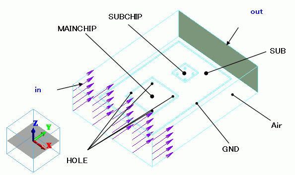
The fluid (Air) is created by a solid body and defined as [Fluid] in the material property.
Body Attributes and Materials
|
Body Number/Type |
Body Attribute Name |
Material Name |
Mesh Size |
|
0/Solid |
SUB |
006_Glass_epoxy * |
|
|
1/Solid |
GND |
008_Cu * |
|
|
2/Solid |
MAINCHIP |
001_Alumina * |
|
|
3/Solid |
SUBCHIP |
001_Alumina * |
|
|
4/Solid |
HOLE |
008_Cu * |
|
|
5/Solid |
HOLE |
008_Cu * |
|
|
6/Solid |
HOLE |
008_Cu * |
|
|
7/Solid |
HOLE |
008_Cu * |
|
|
8/Solid |
HOLE |
008_Cu * |
|
|
9/Solid |
HOLE |
008_Cu * |
|
|
10/Solid |
HOLE |
008_Cu * |
|
|
11/Solid |
HOLE |
008_Cu * |
|
|
12/Solid |
Air |
000_Air(*) |
|
* Available from the material DB
The heat quantities of MAINCHIP and SUBCHIP are set up as follows.
|
Body Attribute Name |
Tab |
Settings |
|
MAINCHIP |
Heat Quantity |
0.2 [W] |
|
SUBCHIP |
Heat Quantity |
0.1 [W] |
|
Air |
Solid/Fluid |
|
Fluid is set to Air. The main flow temperature is set to 25deg C.
|
Material Property Name |
Tab |
Settings |
|
Air |
Solid/Fluid |
State: Fluid Main Flow Temperature: 25 [deg] |
Boundary Conditions
The flow velocity is given at the inflow face and the velocity potential is given at the outflow face.
The outflow face is set to the opening by setting the velocity potential of the outflow face to 0 [m^2/s].
-
The details are explained at [Fluid] tab of the boundary condition.
|
Boundary Condition Name/Topology |
Tab |
Boundary Condition Type |
Settings |
|
in/Face |
Fluid |
Flow Velocity |
1 [m/s] |
|
out/Face |
Fluid |
Velocity Potential |
0 [m^2/s] |
Results
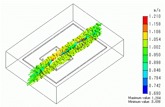
The distribution of the flow velocities is shown below.
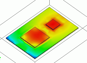
The temperature distribution is shown below.
-
The temperature distribution of the fluid is not available.
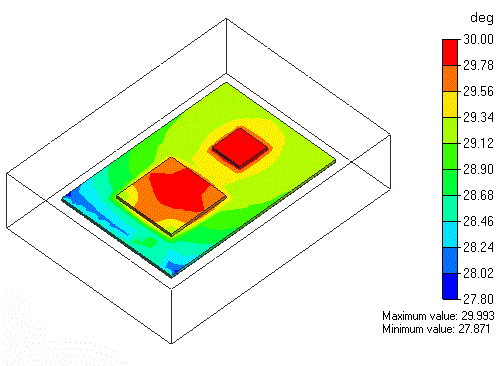
SUBCHIP is hotter than MAINCHIP as its heat quantity is higher and it is positioned down the flow.
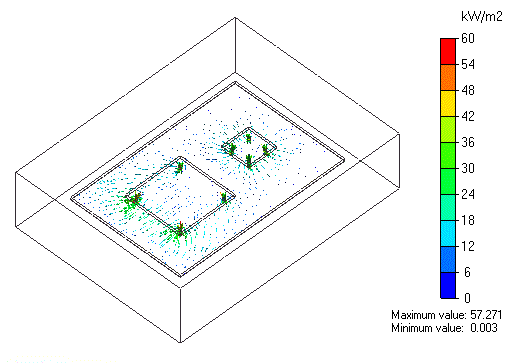
The vectors of the heat flux are shown below.