


|
Home / Examples / Piezoelectric Analysis [Rayleigh] / Example 10: Sheet-Body Electrodes
Example 10: Sheet-Body Electrodes
General
-
Resonant analysis is performed for a piezoelectric bar with sheet body electrodes attached on it.
-
The results are compared with other electrode settings.
-
Unless specified in the list below, the default conditions will be applied.
-
Obtain this session's project file. (Right-click and choose 'Save link as')
-
Results will vary depending on Femtet version and the PC environment.
Analysis Space
|
Item |
Settings |
|
Analysis Space |
3D |
|
Model Unit |
mm |
Analysis Conditions
The analysis type is resonant analysis.
|
Item |
Settings |
|
Solver |
Piezoelectric Analysis [Rayleigh] |
|
Analysis Type |
Resonant Analysis |
|
Options |
N/A |
|
Output Setting |
Select [Impedance]
Minimum: 4.4×10⁶ [Hz] Maximum: 4.8×10⁶ [Hz] Division number: 500
|
 is pressed to enter the values in the appearing RayImpGraph dialog box.
The resonant analysis tab is set up as follows.
|
Tab |
Setting Item |
Settings |
|
Resonant analysis |
Number of Modes |
10 |
|
Approximated Frequency |
4.45 [MHz] |
Model (Thickness Shear_Sheet Body Model)
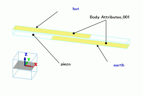
Electrodes (Body Attribute_001) are set on the top and bottom faces of a rectangular piezoelectric rod, with tthe positions shifted.
The electric potential boundary condition is set on the electrodes.
The electrodes are sheet body with body attribute name and material assigned.
(In the piezoelectric analysis, the force such as pressure are not allowed as a boundary condition on the sheet body)
Model (Thickness Shear_Solid Body Model)
The sheet body is replaced by the solid body in the analysis model above. The solid body is created by stretching the sheet body.
The stretching length is 1.e-3 [mm], the thickness specified by the body attribute of the sheet body model, so that the electrodes and piezoelectric material do not overlap.
Model (Thickness Shear_Electrode Boundary Model)
The body attribute and material property of the sheet body are deleted from the Thickness_Shear_Solid Body Model. The boundary condition remains undeleted.
Body Attributes and Materials
|
Body Number/Type |
Body Attribute Name |
Material Name |
|
0/Solid |
piezo |
000_P-4 * |
|
1/Sheet |
BA1 |
002_Au * |
|
2/Sheet |
BA1 |
002_Au * |
* Available from the material DB
The polarizations are set as follows.
|
Body Attribute Name |
Tab |
Settings |
|
piezo
|
Direction |
Specifying Method: Vector Vector: X=1.0, Y=0.0, Z=0.0 |
|
Body_Attribute_001 |
Thickness/Width |
Thickness of Sheet Body: 1x10⁻³ |
Boundary Conditions
|
Boundary Condition Name/Topology |
Tab |
Boundary Condition Type |
Settings |
|
earth/Face |
Electric |
Electric Wall |
Electric Potential Specified: Electric Potential 0 [V] |
|
hot/Face |
Electric |
Electric Wall |
Electric Potential Specified: Electric Potential 1 [V] |
Results
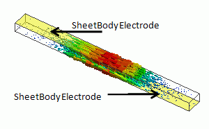
The displacement vectors at thickness-shear-mode vibration is shown below.

From the analysis results of the three models above, the impedance characteristics are plotted. There is not much difference between the cases of sheet body and solid body.
- The frequency response of the impedance can be plotted at Impedance (Piezo-Resonance)
- To add impedance characteristics on the same graph, drag and drop the file with extension s1p from a result folder.
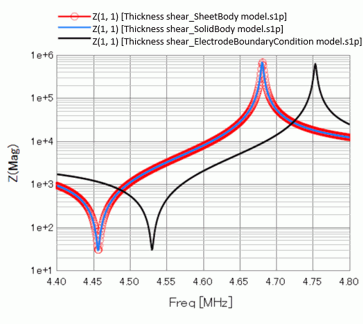
The thickness of electrodes is taken into account by using sheet body.
Compared with a solid-body model, the analysis speed is improved and model drawing is simplified.
Calculation Time of Sheet Body Model: 11 sec.
Calculation Time of Solid Body Model: 13 sec.
|
Electrode Definition |
Resonant Frequency |
Calculation Time * |
|
Imprinting body |
4.529801[MHz] |
0.93 |
|
Sheet Body |
4.456414[MHz] |
1.00 |
|
Solid Body |
4.456087[MHz] |
1.43 |
* The calculation time is relative with referenced to that of sheet-body electrodes.