


|
Home / Examples / Piezoelectric Analysis [Rayleigh] / Example 15: External Resister
Example 15: External Resistor
General
-
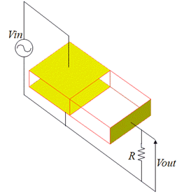
A piezoelectric device consists of two parts having different polarized directions.
-
An external resistor is connected to the piezoelectric device. The voltage generated across the resistor is solved.
-
Unless specified in the list below, the default conditions will be applied.
-
Obtain this session's project file. (Right-click and choose 'Save link as')
-
Results will vary depending on Femtet version and the PC environment.
The project contains a model for harmonic analysis and a model for resonant analysis. The harmonic analysis only is explained here.
Analysis Space
|
Item |
Settings |
|
Analysis Space |
3D |
|
Model Unit |
mm |
Analysis Conditions
The analysis type is resonant analysis.
|
Item |
Setting |
|
Solver |
Piezoelectric Analysis [Rayleigh] |
|
Analysis Type |
Harmonic Analysis |
|
Options |
N/A |
The harmonic analysis tab is set up as follows.
|
Tab |
Setting Item |
Settings |
|
Harmonic Analysis |
Sweep Values |
Minimum: 200×103 [Hz] Maximum: 230x103 [Hz] |
|
Sweep Type |
Number of Divisions: 120 |
Graphical Objects
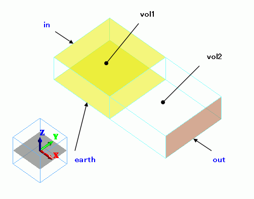
vol1 is polarized in +Z direction, while vol2 is polarized in +X direction.
The top and bottom faces of vol1 are set with electrodes. The electric potential is output at an end of vol2.
Body Attributes and Materials
|
Body Number/Type |
Body Attribute Name |
Material Name |
|
0/Solid |
vol1 |
000_P-4 * |
|
1/Solid |
vol2 |
000_P-4 * |
(*) Available from the material DB
vol1 and vol2 are polarized as follows.
The body attribute directions are set up as follows:
|
Body Attribute Name |
Direction |
|
vol1 |
Vector Specified: Vector: X=0.0, Y=0.0, Z=1.0 |
|
vol2 |
Vector Specified: Vector: X=1.0, Y=0.0, Z=0.0 |
Boundary Condition
|
Boundary Condition Name/Topology |
Tab |
Boundary Condition Type |
Setting |
|
earth/Face |
Electric |
Electric Wall |
Electric Potential Specified: Electric Potential 0 [V] |
|
in/Face |
Electric |
Electric Wall |
Electric Potential Specified: Electric Potential 1 [V] |
|
out/Face |
Electric |
Electric Wall |
Floating electrode Select [Add a resistor across to ground]. The resistances are 1, 5, and 10 [Mohm]
|
Results
The frequency response of the floating electrode's voltage is shown below.
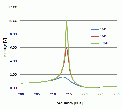
The voltage peaking is less with lower resistance value.
Comparison with Resonant Analysis Model
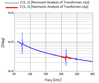
The impedance frequency responses are compared between the harmonic analysis model and the resonant analysis model.
In the resonant analysis, resistor cannot be set to the floating electrode. In this sense, the model is different from the harmonic analysis model.
The impedance characteristic of the harmonic analysis model is not steep due to the resistor. Except for this, similar impedance characteristics are acquired for the resonant analysis and harmonic analysis.
Reference:
See Impedance for drawing a graph.
See Drag-and-drop on the graph window for the graph data superposition.