


|
Home / Examples / Thermal Analysis [Watt] / Example 17: Temperature-Dependent Heat Source (Transient Analysis)
Example 17: Temperature-Dependent Heat Source (Transient Analysis)
General
-
The model is the same as Example 8: A heat source is placed on a substrate, and there is a forced air flow for cooling in parallel to the substrate.
The heat transfer is analyzed under the transient condition. The heat source is temperature-dependent.
-
The coefficient of heat transfer of forced convection is acquired manually.
To acquire it automatically, see [Ex.1 of Simple Fluid-Thermal Analysis].
-
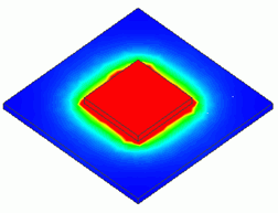
The temperature distribution and the heat flux vectors are solved.
-
Unless specified in the list below, the default conditions will be applied.
-
Obtain this session's project file. (Right-click and choose 'Save link as')
-
Results will vary depending on Femtet version and the PC environment.
Analysis Space
|
Item |
Settings |
|
Analysis Space |
3D |
|
Model Unit |
mm |
Analysis Conditions
|
Item |
Settings |
|
Solver |
Thermal analysis [Watt] |
|
Analysis Type |
Transient Analysis |
|
Options |
N/A |
The transient analysis tab is set up as follows. The number of calculation steps is 20. The timestep is 30 sec.
Therefore, the temperature distributions for 600 sec are solved.
|
Tab |
Setting Item |
Settings |
||||||||
|
Transient analysis |
Table |
|
||||||||
|
Initial Temperature |
25 [deg] |
Model
The same as example 7. The body attributes, the material properties and the boundary conditions are the same as well.
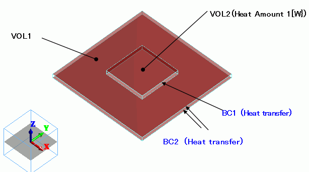
The substrate (VOL1) and the heat source (VOL2) are created as solid body box, and the heat quantity is defined in the body attribute of VOL2.
The coefficient of heat transfer for the top and bottom faces of the substrate and the top face of the heat source are calculated based on the simplified equation.
Body Attributes and Materials
|
Body Number/Type |
Body Attribute Name |
Material Name |
|
0/Solid |
VOL1 |
006_Glass_epoxy * |
|
1/Solid |
VOL2 |
001_Alumina * |
* Available from the material DB
The heat quantity of VOL2 is set up as follows.
|
Body Attribute Name |
Tab |
Settings |
|
VOL2 |
Heat Quantity |
Heat Density Temperature Dependency: Yes |
Heat quantity is specified by heat density in the analyses where temperature-dependent heating materials are involved.
In example 8, we set 1[w] for the heat quantity of VOL2. As the volume of VOL2 is 800*10^-9 [m^3], the heat density is equal to
1.25 x 10^6 [W/m^3].
To evaluate the heat increase by temperature increase, use the Arrhenius equation. Using the following equation,
P(25) = 1.25 x 10^6 [W/m^3],
the following equation is given:
P(T) = 1.25 x 10^6 * exp(-0.15/(k*(T+273))) / exp (-0.15/(k*(25+273)))
where 0.15 [eV] is the activation energy and k is the Boltzmann constant.
|
Body Attribute Name |
Item |
Settings |
|
VOL2 |
Nonlinearity Table |
Select [Smooth Interpolation]
|
|
Temperature |
Heat Quantity |
Temperature |
Heat Quantity |
Temperature |
Heat Quantity |
|
25 |
1.25 |
155 |
7.365383041 |
605 |
59.18105993 |
|
35 |
1.51094343 |
205 |
11.26925562 |
655 |
65.85048973 |
|
45 |
1.804711948 |
255 |
15.90794507 |
705 |
72.47585198 |
|
55 |
2.132370783 |
305 |
21.15582761 |
755 |
79.02738627 |
|
65 |
2.494768691 |
355 |
26.88623825 |
805 |
85.48214754 |
|
75 |
2.892545312 |
405 |
32.98193112 |
855 |
91.82276684 |
|
85 |
3.326141169 |
455 |
39.339762 |
905 |
98.03640656 |
|
95 |
3.795809582 |
505 |
45.87196227 |
955 |
104.1138907 |
|
105 |
4.301629871 |
555 |
52.5055812 |
1005 |
110.0489868 |
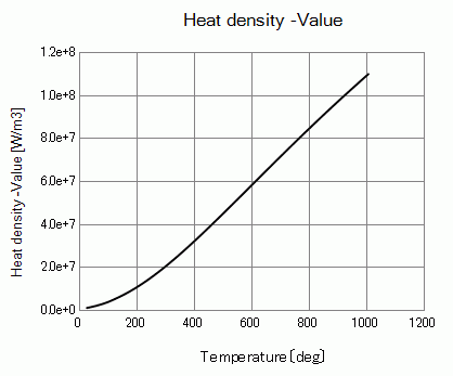
Heat density's temperature plot is shown below.
Boundary Conditions
The coefficient of heat transfer for the forced convection is calculated as follows. The equation is given in Example 8: Heat Radiation by Forced Convection (Transient Analysis).
For the details, please refer to the Coefficient of Heat Transfer for Forced Convection
To acquire it automatically, see [Ex.1 of Simple Fluid-Thermal Analysis].
|
Boundary Condition Name/Topology |
Tab |
Boundary Condition Type |
Settings |
|
BC1/Face |
Thermal |
Heat Transfer/Convection |
Coefficient of Heat Transfer: 17.26 [W/m2/deg] Ambient Temperature: 25 [deg] |
|
BC2/Face |
Thermal |
Heat Transfer/Convection |
Coefficient of Heat Transfer: 27.3 [W/m2/deg] Ambient Temperature: 25 [deg] |
Results
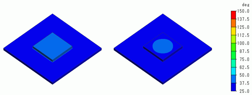
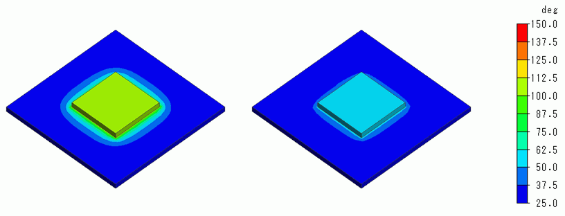
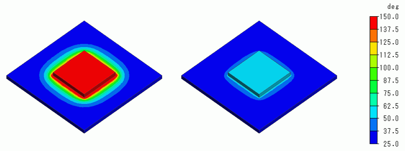
The temperature distributions at each elapsed time are shown in the left figures below. The right figures are the results of Example 8.
The unit of the color scale is [deg].
At Minimum/Maximum Value on the Contour tab of [Graphics Setup], deselect [Automatic] and set 25 => 150.
There is almost no difference from Example 8 in 60 sec.
However, the temperature increases more than in example 8 at 300 and 450 sec as the heat increases with higher temperatures.
In 60 sec
In 300 sec
In 450 sec
Temporal change of temperature is shown below.
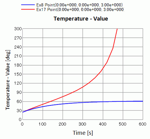
Unlike Example 8 where the convergence is seen at around 600 sec,
here in this example, the temperature continues to rise, indicating that thermal runaway is taking place.