|
Home / Modeling / Drawing Process / How to Modify Objects / Deformation / Extrude with Taper
Extrude with Taper
|
|
|
|
|
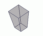
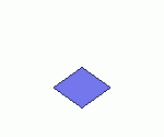
Before |
|
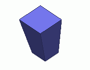
After |

Extrude with TaperThe
selected vertex, wire or sheet bodies
are extruded to form the wire, sheet or solid bodies respectively.
Extrude with TaperOn
the [Model] tab, go to
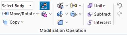
and click Select Body at  .
.
On the [Model] tab, go to
,
and click ▼ at the side of [Extrude]
 .
.
Select [Extrude with Taper]  on the submenu.
(Alternatively, right click the mouse. On the appearing menu, select [Deform]-[Extrude]-[Extrude with Taper])
-
Extrude with Taper.
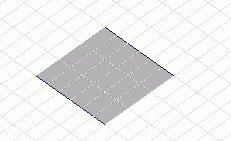
-
Click
 in the parameter input dialog box.

-
Enter the Extrusion vector in the parameter input dialog box and click
.
(Alternatively, click the reference point of the Extrusion vector on the modeling window.
Then, move and click the mouse to set the Extrusion vector.)
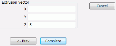
-
Enter the reference point. (See [Reference point] for more information.)
The gravity center indicated in the parameter input dialog box is the default.
Click to continue as is.
To change it, enter the desired coordinates in the dialog box or specify it on the modeling window.
-
Specify the scale factor.
Enter the scale factor in the parameter input dialog box, and click .
.
(Alternatively, click and set the reference length
and the scale factor on the modeling window.) See [The Scale Factor] for more information.