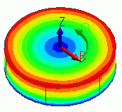
|
Home / Show Results / Result Field / Setting Coordinate System
Setting Coordinate System
Shows the results in the coordinate system.
Local orthogonal coordinate system and cylindrical coordinate system can be set.
On the [Results] tab,

press ▼ of [Graphics Setup] , click [Setting coordinate system]
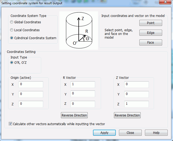
 on the submenu. The dialog box to set the coordinate system will show up.
Enter startpoints, direction of vectors and push Apply button. The results at the specified coordinate system will be shown.
|
Setting Item |
Notes |
|
|
Coordinate System Type |
Selectable from [Local coordinate system] and [Cylindrical coordinate system]. Select [Global coordinate system] to return to the default coordinate system.
|
|
|
Coordinates Setting |
Input Type |
Sets the combination of the direction vectors in the local coordinate system. Select either X and Z directions or X and Y directions. In the local orthogonal coordinate system, three points can be specified.
|
|
Origin |
Sets the origin of the coordinate system.
|
|
|
Direction Vector |
Sets the direction vector .
|
|
|
Reverse Direction |
Reverses the direction vector.
|
|
|
Calculate Other Vectors |
If [Calculate other vectors automatically while setting the vector] is selected,
|
|
|
Input Coordinates and Vector on the Model |
Point |
When setting the origin, coordinates of selected vertex or node will be the origin. When setting the direction vectors, the origin will be the startpoints and the vertex or node will be the endpoints.
|
|
Edge |
When setting the origin, middle point of the selected edge will the the origin. When setting the direction vectors, tangent line to the selected edge will be the direction vector. You can reverse the direction by pressing the Reverse Direction button.
|
|
|
Face |
When setting the origin, gravity center of the selected face will the the origin. When setting the direction vectors, normal line to the selected face will be the direction vector. You can reverse the direction by pressing the Reverse Direction button.
|
|
Display Example
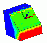
Normal line to the face is the Z axis of the local coordinate system. The stress in the normal line direction is shown.

Cylindrical coordinate system is set. The displacement in the radius direction is shown.