


|
Home / Technical Notes / Stress Analysis / Contact analysis / Contact Analysis Setting
Contact Analysis Setting
This analysis judges if the bodies, which are contact pair, contact each other.
Specifically, it judges if the bodies dent each other. It is called a contact judgment.
Contact force is generated at the part which is judged to be in contact so that the bodies do not dent each other.
Femtet judges the contact automatically.
In some cases, however, it may fail to detect the contact correctly.
By modifying the settings in [Contact Analysis Setting] below, the judgment can be performed correctly.
The specific values, and when and how to apply them are explained below.
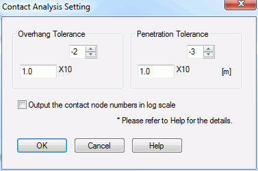
The following can be set and edited in the [Contact Analysis Setting] dialog box.
Overhang Tolerance
If the bodies of approximately the same size contact each other,
or a boundary pair is on the symmetric boundary, the nodes on the contactor are extended beyond the contactee face.
This may cause the non-convergence.
To avoid it, overhang tolerance is applied so that the bodies are judged in contact state even if there is a slight overhanging of nodes.
The overhang tolerance determines the allowable range to maintain the contact state of the bodies.
The overhang tolerance can stabilize the contact judgment in the case like below.
In the following figure, the bodies of approximately the same size are in contact.
We assume the material of the contactor surface is softer than the contactee surface.
At the moment the two bodies contact, the contactor body is pulled in tangential direction by the Poisson effect.
Due to this deformation, the nodes, indicated by the red arrows, on the contacting body are extended beyond the contactee surface.
Strictly speaking, these overhanging nodes are judged not in contact by the contact judgment.
This judgment may cause instability in the analysis due to the mutual denting of the bodies or overall imbalance.
By setting appropriate overhang tolerance, the contact state can be maintained although the nodes are not actually in contact.
As a result, the analysis can be stabilized.

The overhang tolerance is a threshold for determining the acceptable distance of the overhanging nodes from the contactee surface.
Any value between 0 and 1 can be entered.
For the 2nd-order element, if 1 is set to the tolerance, the overhang is allowed up to half the edge length of the element of the contactee surface.
Default setting is 0.01. If the non-convergence occurs due to the overhanging, try the larger value such as 0.1, etc.
Penetration Tolerance
If the distance of dent (=penetration distance) made by the contactor is detected on the contactee surface,
it is judged that such part is in contact.
In the following position of the bodies, judgment of penetration contact depends on the previous step.
Example: The ball (contactor) is positioned underneath the board (contactee)

If the position changed as in the left figure below, it cannot be judged that penetration contact occurred.
In the right figure below, it can be judged the penetration contact occurred.

Basically, it is not necessary to modify the default settings as Femtet automatically judges penetration contact.
However, if the penetration contact is judged wrongly due to the an unexpected manner of body movement, analysis does not converge or the displacement diagram of diverged results becomes unrealistic.
In such case, set the penetration tolerance manually as follows.
The default value of the penetration tolerance is negative for the automatic judgment.
Enter the positive value for setting the penetration tolerance manually.
How the entered value affects the judgment is explained below.
In the contact analysis, the positional relationship of the contactor and contactee is checked for the judgment.
If the contactor is positioned opposite to the normal direction of the contactee and its distance is smaller than the penetration tolerance, it is judged that the penetration contact occurred.
If the distance is larger than the penetration tolerance, it is not judged that the penetration contact did not occur.
In the figure below, if the tolerance is set larger than the red arrow, the bodies are judged in penetration contact.
If the tolerance is set smaller than the blue arrow but larger than 0, the bodies are judged not in penetration contact.

Too small value in Penetration Tolerance might cause the opposite misjudgment, which is the contact pair is judged out of contact even if they are in contact.
In the analysis where the model changes the state from non-contact to contact,
the contactor is to penetrate the contactee to a certain extent at the early stage of contact.
A reasonably large value, which is more than the expected penetration distance, has to be entered in Penetration Tolerance.
If the number of nodes engaged in contact is more than 1 even though the contact is yet to be made, there must be a misjudgment.
Try several values in Penetration Tolerance.
In most cases, however, you don't need to change the default value (negative value).
Output the contact node numbers in log scale
If selected, the total number of nodes which are in contact at the contact surface is output.
The node numbers are output as well. With the obtained information, the contact state can be examined more in detail.