|
Home / Technical Notes / Mesh / Adaptive Meshing
Adaptive Meshing
1. Overview
Smaller elements should be arranged for the area where the electrical field, the stresses etc are concentrated or drastically change. The adaptive mesh method adjusts the element size automatically.
The adaptive mesh method is classified into 3 versions below. Of these versions, the h-version is implemented in Femtet.
p-version: The order of the interpolation function is changed to higher one.
r-version: The nodes are moved.
h-version: The elements are divided into smaller ones.
2. Theory
The initial meshing is done with the model, and FEM calculations are performed. The resulting errors are evaluated. The elements with large errors are divided into smaller ones.
FEM calculations are performed with the modified meshes, then the errors are evaluated again. This process is repeated as many as needed.
In this process, it is needed to decide the way to divide elements, the way to calculate errors, and stopping criterion for the iteration.
(1) Division procedure
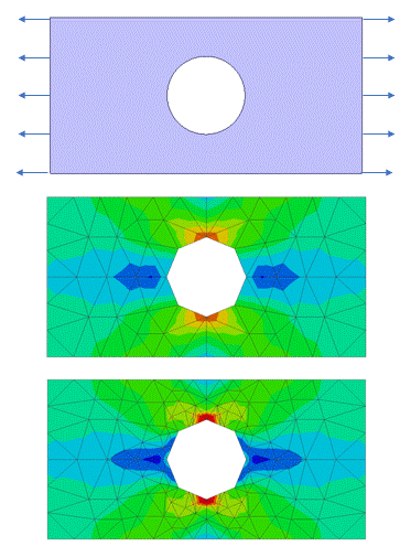
Let's take a look at the electric field analysis. The initial meshing is done for the model as shown in the top figure above. In this case, the electric field is strong at the edge of upper electrode, where the errors are expected to be large.
Each of the four elements around the edge are re-divided into four red elements as shown in the middle figure. At the same time, the blue elements are divided into two elements in order to maintain the continuity of nodes.
If the errors are still large even with the modified meshes, the elements are divided again and the smaller meshes are created as shown in the bottom figure.
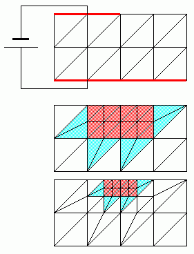
The "element incremental rate" specifies the percentage of divided elements to all elements in one iteration.
The larger the element incremental rate is, the more the number of elements increases in one iteration. If it is 100%, all elements are divided.
(2) Errors
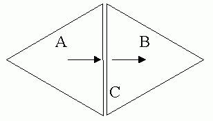
The energy flow from Element A to Element B is continuous at Boundary C. The energy which flows out of A should be the same as the energy which flows into B. But in FEM, errors are inevitable and the energy is discontinuous.
This discontinuity is used to evaluate the errors. The elements which have the boundaries where the discontinuities are large are re-divided.
(3) Stopping criterion
The error energy of the whole model is calculated by summing up all element error energies. This error energy is used as a stopping criterion.
When this value becomes smaller than the "tolerance" set in the setting dialog box, the iteration is over.
If the number of iteration reaches the "maximum number of iterations", the iteration stops, too.
S-parameters, capacitances, inductances etc can be selected as the physical quantity to determine the convergence instead of the error energy.
3. Calculation Examples
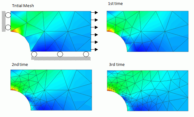
The results of the mechanical stress analysis are shown below. In the figures, red represents the strong mechanical stress. The figures show the elements where the strong mechanical stresses are applied to are divided into smaller elements sequentially.
4. Not Create Adaptive Meshes on a Curved Face
If [Create meshes on a curved face] is deselected,
active meshes are created on the polyhedron, or the plane, that has been used for the initial meshing. This method is not recommended due to larger errors in shape unless otherwise your active meshing should fail or the compatibility with former models should be kept.
(In Femtet version 2022.1 or earlier, active meshes can not be created on a curved face)
The figures below are examples where active meshes are not created on a curve face. The middle figure shows initial meshes and the lower figure shows adaptive meshes. The opening shape remains an octagon, not approaching a circular.