|
Home / How to Set Body Attribute, Material Property and Boundary Condition / Material Property Tabs / Conductivity Tab
Conductivity Tab
The material's electric conductivity is set on this tab.
It is in the [Edit Material Property] dialog box. See [How to Set Body Attribute/Material Property].
|
Setting Item |
Notes |
||||||
|
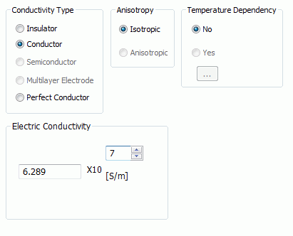
Conductivity Type |
Selects one from Insulator, Conductor, Semiconductor or Perfect conductor. |
||||||
|
Anisotropy |
Selects either Isotropic or Anisotropic.
|
||||||
|
Temperature Dependency |
Selectable for the magnetic field harmonic-thermal coupled analysis.
Select either Yes or No. When Yes is selected and
|
||||||
|
Nonlinearity |
Selectable in the Electric Field Analysis (Coulomb)
Select Linear if the electric conductivity is constant regardless of the intensity of the electric field.
Select Nonlinear if the electric conductivity is dependent on the intensity of the electric field.
|
||||||
|
Conductivity |
The entry field for the conductivity will show up when Conductor is selected for Conductivity Type and Linear is selected in Nonlinearity.
The significand is a real number greater than 0.
|
||||||
|
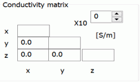
Conductivity Matrix |
The matrix will show up when Anisotropic is selected.
The significand is a real number equal to or greater than 0. It is not allowed to enter 0 in (x, x), (y, y), and (z, z). Direction of the anisotropic material depends on the setting on the [Direction] tab of body attribute. With the default setting on the Direction tab, (x, y, z) in the above figure matches with (X, Y, Z) of the modeling window.
|
||||||
|
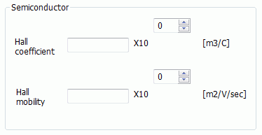
Semiconductor |
The entry field for the semiconductor will show up when Semiconductor is selected.
Specify the coefficient of Hall and the Hall mobility.
|
||||||
|
Multilayer Electrode |
Electrode has multilayer structure. It is applicable to the electromagnetic analysis only.
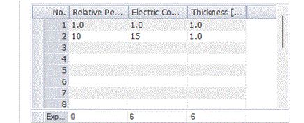
Two layers are defined in the table above and analysis is performed as follows. In the table, the first row is Layer No. 1 and the second row is Layer No. 2. Please keep this layer order in mind.
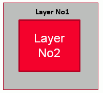
1. Solid Body in 3D AnalysisFig 1 represents the cross section of solid body. Inside of the body is Layer No.2 which is surrounded by Layer No. 1. The value set in the table is used for the thickness of Layer No. 1, but not used for Layer No. 2 assuming that it is thick enough.
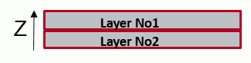
2. Sheet Body in 3D AnalysisIf [Take thickness of face/edge electrode into account] is not opted in the electromagnetic analysis, calculation is executed assuming the thickness direction is as in Fig 2. The thickness of Layer No1 is taken into account whereas that of No2 is considered to be thick enough. If "Take thickness of face/edge electrode into account" is opted in the electromagnetic analysis, the order of layers is defined on the Direction tab of the body attribute. The layer No.2 is placed first and followed by layer No. 1 in the direction of vector specified on the Direction tab. Figure 3 shows the sheet bodies normal to the Z axis. If (0,0,1) is set to the vector on the Direction Tab, calculation is performed assuming that the order of layers is as in Figure 3. 3. Sheet Body in 2D AnalysisThis is the same case as 1 above. Please consider Fig 1 as the front face of the drawing on the XZ plane in 2D analysis.
4. Wire Body in 2D AnalysisThis is the same case as 2 above. Please consider Fig 2 and 3 as the front face of the drawing on the XZ plane in 2D analysis.
|
 is clicked,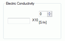

In the resistance analysis of the electric solver (Coulomb) and the electric-thermal analysis (Coulomb/Watt), resistivity is allowed to enter.
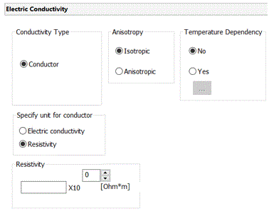
|
Setting Item |
Notes |
|
Anisotropy |
Sets either Isotropic or Anisotropic. |
|
Temperature Dependency |
Sets either No or Yes.
If Yes is set, by clicking Enter the data there.
|
|
Resistivity |
Available only if the temperature dependency is No and the anisotropy is Isotropic. The significand is a real number greater than 0.
|
|
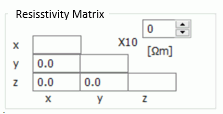
Resistivity Matrix |
Available only if the temperature dependency is No and the anisotropy is Anisotropic.
|