|
Home / Examples / Stress Analysis [Galileo] / Example 75: Transient Analysis of Standing Bars
Example 75: Transient Analysis of Standing Bars
General
-
Forced oscillation is applied to two standing bars with different heights. Perform a transient analysis of the standing bars.
-
Refer to Example 16: Harmonic Analysis of Standing Bars for the result of the harmonic analysis.
-
It is observed that the frequency of the forced oscillation affects the vibration.
-
Unless specified in the list below, the default conditions will be applied.
-
The oscillation amplitude near the resonant frequency depends on the mechanical loss of material. Adjust the mechanical loss if needed. (See Example 50)
-
Obtain this session's project file. (Right-click and choose 'Save link as')
-
Results will vary depending on Femtet version and the PC environment.
Analysis Space
|
Item |
Settings |
|
Analysis Space |
3D |
|
Model Unit |
mm |
Analysis Conditions
The analysis type is the transient analysis.
|
Item |
Settings |
|
Solver |
Stress Analysis [Galileo] |
|
Analysis Type |
Transient Analysis |
|
Analysis Options |
None |
The resonant frequencies of each tower are 1250 [Hz] and 1650 [Hz], which have been acquired in the harmonic analysis in advance.
The bars vibrated at 1250 [Hz] are analyzed here.
The transient analysis is set on the transient analysis tab as follows.
By selecting [Automatic] for the timestep and [Adjust referring to time-dependent condition] in the detailed automatic timestep setting, the timestep for analysis can be set based on the specified boundary conditions.
When the waveform is defined using the [Input Waveform] function in a boundary condition, one-tenth of a period of the waveform is applied as the timestep.
|
Tab |
Setting Item |
Settings |
|
Transient Analysis |
Timestep |
Automatic |
|
Finish Time |
10 [ms] |
|
|
Maximum Number of Calculation Steps |
1000 |
|
|
Detailed Automatic Timestep Setting |
Select [Adjust referring to time-dependent condition] |
Model
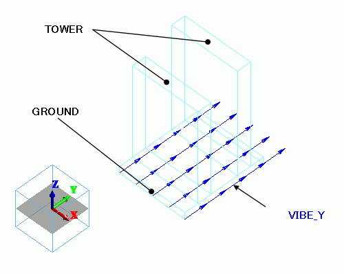
Two bars (TOWER) with different heights are standing on a plate (GROUND).
internal ports. The amplitude of forced vibration is applied to the Y-direction displacement boundary condition (VIBE_Y) on the face topology of the bottom face of GROUND.
Body Attribute and Material Property Setting
|
Body Number/Type |
Body Attribute Name |
Material Name |
|
0/Solid |
TOWER |
001_Al * |
|
1/Solid |
TOWER |
001_Al * |
|
2/Solid |
GROUND |
001_Al * |
* Available from the material DB
Boundary Conditions
The forced vibration involves the vibration of the bottom face, GROUND, in the Y direction and the concurrently fixed displacement in the X and Z directions.
For it, the following boundary conditions are set.
The setting below means the vibration having an amplitude of 1 [mm] in the Y direction is applied to the bottom face, GROUND.
It is conditioned to vibrate five times and then stop.
|
Boundary Condition Name/Topology |
Tab |
Boundary Condition Type |
Settings |
||||||||||||
|
VIBE_Y/Face |
Mechanical |
Displacement |
Select all X/Y/Z components. UX=UX=0.0, UY=1×10⁻³ [m]
Select [Time Dependency]
Weight Function Input using [Input Waveform]
|
Results
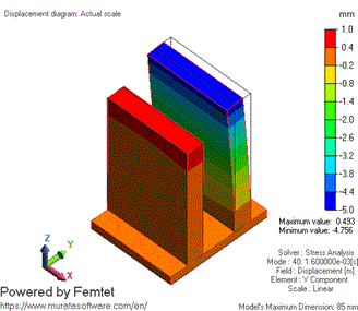
The displacement diagrams below show the displacement at 1.6 [ms], 4 [ms], and 10 [ms], respectively.
The contour diagrams show the displacement in the Y direction.
1.6 [mm] (At 2 Cycles)
4 [mm] (At 5 Cycles)
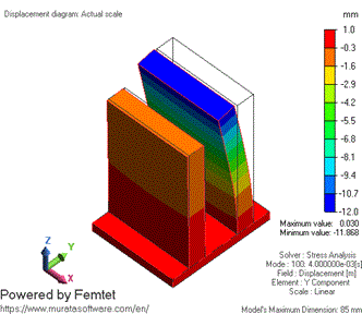
10 [ms] (Finish Time of Calculation)
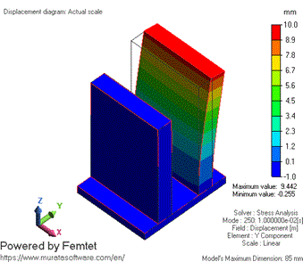
The right tower is vibrating more.
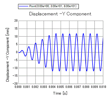
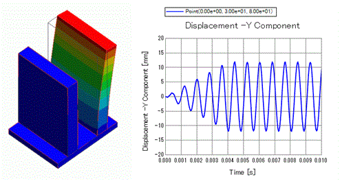
The temporal change in Y-displacement at the tip point (0, 30, 80) of the right tower is plotted.
It is observed that the amplitude of the tower vibration increases while the forced vibration is applied up to 4 [ms]. After 4 [ms], the forced vibration ends and the amplitude remains constant.