|
Home / Examples / Magnetic Analysis (Gauss, Static Analysis/Harmonic analysis) / Example 35: Cogging Torque of Stepper Motor
Example 35: Cogging Torque of Stepper Motor
General
-
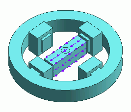
The cogging torque of a stepper motor is analyzed.
-
The relationship between the rotor angle and the torque is calculated using the motor rotation analysis function.
See [Motor Rotation Analysis] for the detail.
-
Please be aware that this is a static analysis. The transient phenomena (dynamic magnetic field) is not analyzed.
The coupled analysis with the external circuit cannot be performed either.
If you want to analyze the transient phenomena or perform the coupled analysis with the external circuit, use the transient analysis (Luvens).
-
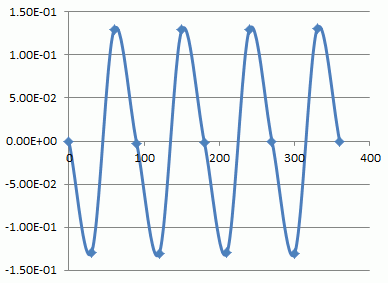
The torque curve and the magnetic flux density vectors are solved.
-
Unless specified in the list below, the default conditions will be applied.
-
Obtain this session's project file. (Right-click and choose 'Save link as')
-
Results will vary depending on Femtet version and the PC environment.
Analysis Space
|
Item |
Settings |
|
Analysis Space |
3D |
|
Model Unit |
mm |
Analysis Conditions
|
Item |
Settings |
|
Solver |
Magnetic Analysis [Gauss] |
|
Analysis Type |
Static Analysis |
|
Options |
Select [Torque Calculation]. |
Set the Torque Calculation tab as follows.
|
Tab |
Setting Item |
Settings |
|
Torque Calculation |
Coordinates on Center Axis: |
X=0, Y=0, Z=0 |
|
Vectors of the Axis |
X=0, Y=0, Z=-1 |
Set the Mesh Tab as follows.
|
Tab |
Setting Item |
Settings |
|
Mesh |
Meshing Setup |
Set the general mesh size automatically: Deselect General Mesh Size: 3 [mm] |
Model
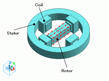
A stator and coils are placed in the air.
A magnet (rotor) is set in the center and its center is the rotation axis of the motor.
No current is flowing in coils.
Body Attributes and Materials
|
Body Number/Type |
Body Attribute Name |
Material Name |
|
19/Solid |
Rotor |
Mag |
|
12/Solid |
Shaft |
SM |
|
14/Solid |
Stator |
SM |
|
25/Solid |
Coil |
008_Cu * |
|
26/Solid |
Coil |
008_Cu * |
|
27/Solid |
Coil |
008_Cu * |
|
28/Solid |
Coil |
008_Cu * |
* Available from the material DB
The magnetizing direction of Rotor is set as follows.
|
Body Attribute Name |
Tab |
Settings |
|
Rotor |
Direction |
Vector: X=0, Y=-1, Z=0 |
The material properties are set up as follows:
|
Material Name |
Tab |
Properties |
|
SM |
Permeability |
Relative Permeability: 3000 |
|
Mag |
Permeability |
Material Type: Permanent Magnet |
|
Magnet |
Magnetization Strength: 1 |
Boundary Conditions
No setting.
Motor Rotation Analysis
|
Tab |
Item |
Setting |
|
Rotation Setting |
Select the Bodies to Rotate |
Rotor Shaft |
|
Rotation Angles |
Start Angle: 0 [deg] Stop Angle: 360 [deg] Step Angle: 30 [deg] |
-
Values for each variable can be set for the individual rotational angle on the variable setting tab.
The electric current flowing through the coil can be changed at the different rotational angles.
Results
Use the motor rotation analysis dialog box. Once the modeling is done,
go to  on the [Model] tab and click ▼ at the bottom of [Run Mesher/Solver]
  . Then click [Motor Rotation Analysis]
  . Then the dialog box appears.
Click [Start Calc] to start the calculation.
The result is output by csv format.
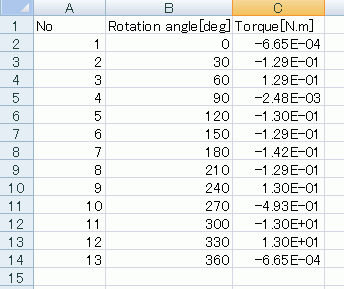
In the figure below, the horizontal coordinate is rotational angle, and the vertical coordinate is torque.