


|
Home / Examples / Piezoelectric Analysis [Rayleigh] / Example 9: Thickness Shear Mode
Example 9: Thickness Shear Mode
General
-
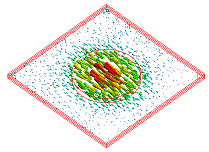
The thickness-shear mode vibration of AT-cut quartz crystal is analyzed.
-
The frequency response of electrode's impedance and the displacement vectors are solved.
-
Unless specified in the list below, the default conditions will be applied.
-
Obtain this session's project file. (Right-click and choose 'Save link as')
-
Results will vary depending on Femtet version and the PC environment.
Analysis Space
|
Item |
Settings |
|
Analysis Space |
3D |
|
Model Unit |
mm |
Analysis Conditions
The analysis type is resonant analysis.
|
Item |
Settings |
|
Solver |
Piezoelectric Analysis [Rayleigh] |
|
Analysis Type |
Harmonic Analysis |
|
Options |
N/A |
|
Output Setting |
Select [Impedance] |
The harmonic analysis tab is set up as follows.
|
Tab |
Setting Item |
Settings |
|
Mesh |
Meshing Setup |
Set the general mesh size automatically: Deselect General Mesh Size: 0.06 [mm]
|
|
Harmonic Analysis |
Frequency |
Minimum: 18.0×10⁶ [Hz] Maximum: 18.6x10⁶ [Hz] |
|
Sweep Type |
Select [Linear Step by Division Number]. Number of Divisions: 50 |
Model
Circular electrodes are placed on the top and bottom faces of the AT-cut quartz crystal. Electric potential is applied to the electrodes.
-
The quartz crystal is divided equally into 3 layers. This makes the division size in the thickness
direction less than 1/6 of the wavelength regardless of the setting mesh size.
Note: If the vibration is thickness-shear mode, the thickness is half of the wavelength.
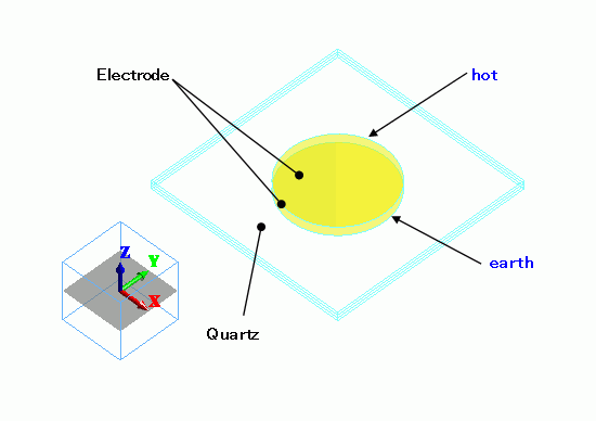
Body Attributes and Materials
|
Body Number/Type |
Body Attribute Name |
Material Name |
|
0/Solid |
Quartz |
301_Quartz * |
|
3/Solid |
Quartz |
301_Quartz * |
|
4/Solid |
Quartz |
301_Quartz |
|
5/Sheet |
Electrode |
003_Ag * |
|
6/Sheet |
Electrode |
003_Ag * |
* Available from the material DB
The cutting angle is set by Euler angle.
|
Body Attribute Name |
Tab |
Tab |
|
Quartz |
Direction |
Euler Angle Specified: Euler Angle: Z=0, X=125.25, Z=0 |
|
Electrode |
Thickness/Width |
Thickness of Sheet Body: 0.2x10⁻³ |
Boundary Conditions
|
Boundary Condition Name/Topology |
Tab |
Boundary Condition Type |
Settings |
|
earth/Face |
Electric |
Electric Wall |
Electric Potential Specified: Electric Potential 0 [V] |
|
hot/Face |
Electric |
Electric Wall |
Electric Potential Specified: Electric Potential 1 [V] |
Results
The calculated frequency response of the impedance across the electrodes from an S(Y) parameters graph is shown below.
To change the range of X axis, set the range in the Graph Properties.
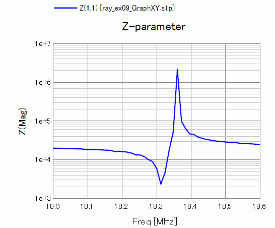
The resonant frequency is around 18.32 [MHz]. The anti-resonant frequency is around 18.36 [MHz].
The thickness shear mode at 18.3 [MHz] is calculated. The displacement vectors are shown below.
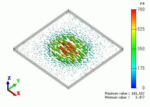
The displacement is specific to the thickness shear mode.