


|
Home / Show Results / Graphics Setup / Contour
Contour
|
Item |
Notes |
|
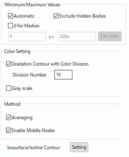
Minimum/Maximum Values |
If Automatic is selected, the minimum and maximum values for the color scale will be calculated automatically. This setting remains valid for the display of other data types. If 0 for Median is selected, the Minimum value will be automatically set so as to make median 0 based on the Maximum value. For manual setting, deselect Automatic and enter the minimum and maximum values in the boxes. Calculate button calculates the values automatically. Select Exclude hidden bodies to calculate them based on the bodies currently shown.
|
|
Color Setting |
Select Gradation contour with color division to show the gradation contour with the colors set at "Color Division". If Gray scale is selected, the display will turn to monochrome instead of full color. Select it for the black and white printing. When displaying the streamlines in the fluid-thermal analysis, by selecting Bodies to Paint with Model Color, the selected body is painted in a model color instead of contour colors.
|
|
Method |
If Averaging is selected, the node contour values are averaged for the neighboring elements of the same material, and the contour display will be smoothed. Please be aware that the accuracy of the calculation is sacrificed with this smoothing. Therefore deselect it for the accurate display. See also [Calculating Field Values].
Select Enable middle nodes to show the contour with middle nodes enabled. Te contour will be displayed with higher definition. Deselect it to display the contour faster for the model with high count of elements. This function is not applicable for the isosurface contour. |
|
|
Click the [Setup] button. The [Isosurface/Isoline Contour] dialog box will appear. |
