|
Home / Show Results / Result Field / Cross Section
Cross Section
On the [Results] tab, go to
click [Show Cross Section] ![]() to show or hide the cross sections.
to show or hide the cross sections.
The dialog box to setup cross section will appear if [Show Cross Section] is selected.
Alternatively, click ▼ at the side of [Show Cross Section] ![]() and then click [Set up Cross Section]
and then click [Set up Cross Section] ![]() on the submenu.
on the submenu.
The setup dialog will show up. Cross sections can be added or deleted.
Click ▼ at the side of [Show Cross Section] ![]() and then click [Show Other Side]
and then click [Show Other Side] ![]() on the submenu.
on the submenu.
The field at the cross section and the surface on the other side are displayed.
|
|
Contour and vector diagrams can be displayed for the cross sections.
The left figure shows the gradation contour for 2 cross sections.
The right figure shows the gradation contour for a cross section and a surface. |
Operations
There are types of operations; Simple mode and Detailed mode.
Simple mode is limited to XY, YZ, and ZX planes for easy operation.
Detailed mode can display a cross section by specifying a point and a normal vector on the cutting plane. Multiple cross sections can be shown as well. Also, the cross section and the surface are displayable simultaneously.
Simple Mode |
|
|
|
XY, YZ, or ZX planeSets the cutting plane on XY, YZ, or ZX plane. Cutting plane X, Y, or Z coordinateSets the location of the cutting plane. Coordinates of the center of the model are set by default. Close buttonCloses the dialog box if clicked. PreviewPreviews the cross section in the operation of the cutting plane if clicked.
CreateCreates the cross section if clicked.
ResetResets the location and normal direction of a cross section to their default values. if clicked. |
|
|
|
Detailed Mode |
|
|
|
How to set up the cutting planeSets the [Direction of Cutting Plane] and the [Point on Cutting Plane]. FaceAligns the direction of the cutting plane to the direction of the face selected in the result window. Reverse DirectionReverses the direction of normal vector. When the cross section and the surface are displayed, the surface in the normal vector's positive direction will be displayed. Its direction can be changed by this button. Selected BodiesMoves the cutting plane to the center of the body selected in the result window. Maximum Point/Minimum PointMoves the cutting plane to the point where the field value displayed on the result window is maximum or minimum. ArrangementDisplay the cross section and the surface simultaneously (vectors are only for cross section): The cross section and the surface in the normal vector’s positive direction are displayed simultaneously. Display without cutting meshes on the cutting plane: Mesh elements on the cutting plane are not cut. Their forms are kept.
Remove meshes on the cutting plane: The portion of the mesh elements crossing the cutting plane are removed. The element forms are kept.
Preview
Enable Preview: Switches on/off preview of the cross section. Guide Grip On: Switches on/off grids used during preview. Distance: Sets the unit grid for translation Angle: Sets the unit grid for rotation. OperationsCreate: Creates a cross section. If a cross section already exists, it will be replaced by the created one. Add: Adds a cross section to the existing sections. Multiple number of sections can be displayed. Delete: Deletes a specified cross section. Stop Update of Max and Min on Color ScaleIf selected, the range of max and min on the color scale will not be updated in creating a cross section. The distribution of the field value at the cross section can be checked in contrast to the whole model.
|
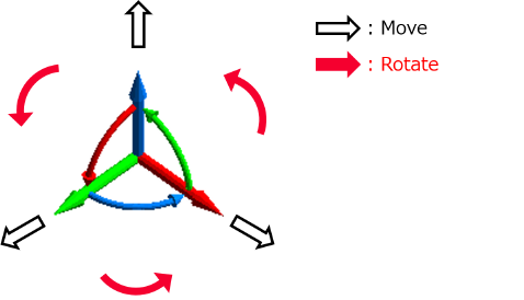
How to Use UI for Preview
|
|
|
If the Cross Section dialog box is enabled, the translation and rotation axes appear as in the left figure. If [Enable Preview] is deselected in the dialog box, the cross section process will be carried out in clicking the [Create] button. If [Enable Preview] is selected, the cross section is created for every operation of cutting planes.
|
|
|
|
|
|
|
|
|