|
Home / Simulation Accuracy Setting (Mesh/Element) / Meshing Setup / Mesher G1 Setting
Mesher G1 Setting
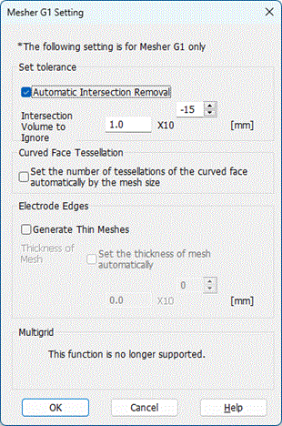
To open this dialog box, click in the Meshing Control dialog box.
*The following setting is for Mesher G1 only
See [Mesher Version] for the difference between Mesher G1 and Mesher G2.
|
Setting Item |
Notes |
||||
|
Set Tolerance |
An error occurs if intersecting bodies exist. By removing the intersection automatically, meshing will be continued.
[Rules for automatic removal in Mesher G1]
These functions will be off if [Automatic intersection removal] is deselected.
[Rules for automatic removal in Mesher G2]
Rules 1 and 2 are applied. If neither rule 1 nor 2 is applied, the body with a smaller volume is yielded and no intersection error will occur.
|
||||
|
Curved Face Tessellation |
The number of tessellations is defined at [Meshing Control] > [Minimum Number of Tessellations for Curved Face]. [Set the number of tessellations of the curved face automatically by the mesh size] calculates the number of tessellations automatically. However, if the calculated value is smaller than the specified minimum number of tessellations, the minimum number will be applied.
|
||||
|
Electrode Edges |
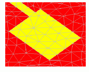
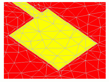
Electromagnetic field intensifies sharply around electrode edges, where the calculation accuracy degrades. It will improve if finer meshes are set there. That will, however, require more time for calculation. To generate the thin meshes, select [Generate Thin Meshes]. To set the thickness of mesh, automatic setting and manual setting are available. In the right figure below, you can see the finer thin meshes at the electrode edges.
|
||||
|
Multigrid Method |
This function is no longer supported. |