Set the boundary conditions.
The boundary condition is required to be set on a part of the body (topology).
It varies depending on the analysis.
The boundary conditions are distinguished by name. It is not allowed to assign the same name to the different boundary conditions
-
On the [Model] tab, go to
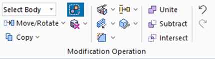 , ,
and select [Select Face] on the drop-down list at  . .
-
How to Switch the Object to Select
-
Concept of Body and Topology
|
|
-
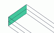
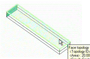
Highlight the face to fix and click to select.
Highlight the end face of the lower box and click to select. Also, while pressing <Ctrl> key, highlight the end face of the upper box and click to select.
(The selecting order is irrelevant)
|
|
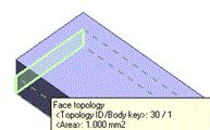
|

Click |
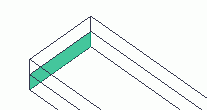 |
|
Highlight |
|
Selected |
|
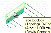
|
Ctrl+click |
|
|
Highlight |
|
Selected |
|
-
On the [Attribute] context tab
 , ,
click [Boundary Condition]  . .
|
|
-
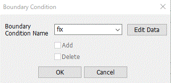
In the [Boundary Condition] dialog box,
enter Boundary Condition Name: fix
and click  . .
-
Any name is acceptable.
|
|
-
Fix the displacement in all X/Y/Z directions in the [Edit Boundary Condition] dialog box.
Go to the [Mechanical] tab,
and set Boundary Condition Type: Displacement .
Select UX, UY, UZ, and confirm that
UX:0, UY:0, UZ:0 [mm]
and click  . .
Then click to exit the [Boundary Condition] dialog box.
-
To fix the displacement, set the Boundary Condition Type: Displacement,
and enter 0 in the direction of no displacement.
|

|
-
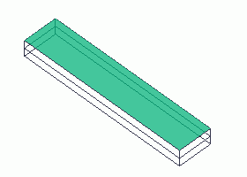
Let's set the boundary condition: hot
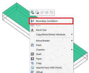
Highlight the top face of the model and click to select.
|
|
-
On the right-click menu, click [Boundary Condition]
|
|
-
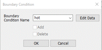
In the [Boundary Condition] dialog box, enter
Boundary Condition Name: hot
and click .
-
Any name is acceptable.
|
|
-
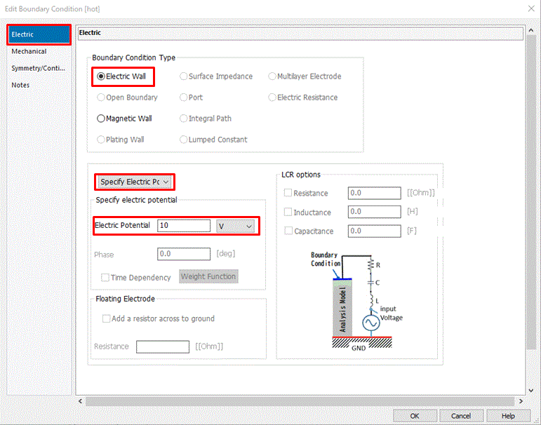
In the [Edit Boundary Condition] dialog box,
go to the [Electric] tab,
set Boundary Condition Type: Electric Wall,
and set Electric Potential: 10.0[V]
and click .
Then click to exit the [Boundary Condition] dialog box.
|
|
-
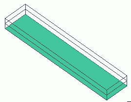
Let's set the grounding.
Highlight the bottom face of the model and click to select.
|
|
-
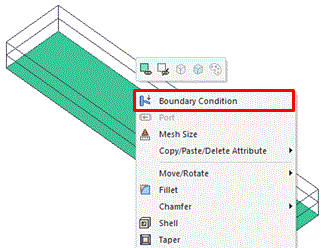
On the right-click menu, click [Boundary Condition].
|
|
-
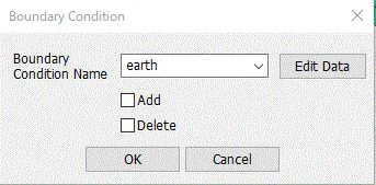
In the [Boundary Condition] dialog box,
enter Boundary Condition Name: earth
and click .
-
Any name is acceptable.
|
|
-
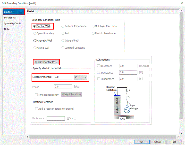
In the [Edit Boundary Condition] dialog box,
go to the [Electric] tab,
set Boundary Condition Type: Electric wall,
also set Electric Potential: 0.0x100
and click .
Then click to exit the [Boundary Condition] dialog box.
|
|
|
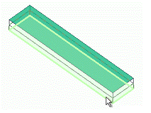
The boundary conditions have been set.
|
|


 Prev
Prev