|
Home / Simulation Accuracy Setting (Mesh/Element) / Meshing Setup / High-Level Setting for Meshing
High-Level Setting for Meshing
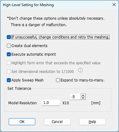
To open this dialog box, click  in the Meshing Control dialog box.
-
Do not change these options unless absolutely necessary as they may halt the calculation.
|
Setting Items |
Notes |
||||||
|
If unsuccessful, change conditions and retry the meshing. |
If the mesh size is larger than the model dimensions, the meshing will fail. In such a case, the smaller mesh size will be applied automatically and the meshing will be retried. If the failure is due to the too fine meshes, [Model resolution] will be increased automatically and the meshing will be retried. This kind of adjustment will be repeated 5 times at most.
|
||||||
|
Create dual elements |
For face in 3D and wire bodies in 2D, two nodes are added in the direction of thickness. The coordinates shift as much as the thickness. The calculation accuracy will increase but the calculation will take more time.
|
||||||
|
Execute automatic imprint |
Enables automatic imprinting if selected.
Automatic imprinting creates identical mesh shape on the connected curved faces to ensure mesh continuity between the curved faces. But in a rare case, the bodies may be deformed by imprinting and meshing may fail. If the curved faces are many, meshing may take long time. To avoid these problems, disable automatic imprinting if the contacting curved faces are the identical form or no curved faces are in contact.
If Mesher G1 is in use, automatic boolean is selectable in addition to the automatic imprint.
|
||||||
|
Highlight form error that exceeds the specified value |
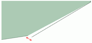
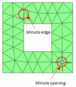
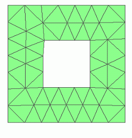
If a topology with large form error exists during the meshing, the model resolution is automatically adjusted to absorb the form error. By selecting this option, the form error is highlighted instead of automatic adjustment. This is useful for identifying the location where the form error is large.
Form Error
|
||||||
|
Set Dimensional Resolution to 1/1000 |
Selectable only when [Model Unit] is [mm].
Basically, dimensional resolution is 1.0e-5 [mm]. But it can be changed to 1.0e-8 [mm].
If bodies and topologies have already been created, or if CAD data is imported, subsequent modeling and meshing will not work properly.
|
||||||
|
Model Resolution |
Minute edges/faces shorter than the length specified here are removed from the model. This function is of use when CAD data is imported that contains minute edges/faces.
|
||||||
|
If [Hexahedral-Free/Sweep Mesh] is selected for the element type, sweep meshes are created where they are applicable. If [Expand to many-to-many] is selected, sweep meshing is possible for the many-to-many configuration. |