


|
Home / Examples / Electromagnetic Analysis [Hertz] / Example 26: Patch Antenna Array
Example 26: Patch Antenna Array
General
-
The characteristics of a patch antenna array are analyzed.
-
The directivity and S-parameters are solved.
-
Unless specified in the list below, the default conditions will be applied.
-
Obtain this session's project file. (Right-click and choose 'Save link as')
-
Results will vary depending on Femtet version and the PC environment.
Analysis Space
|
Item |
Settings |
|
Analysis Space |
3D |
|
Model Unit |
mm |
Analysis Conditions
|
Item |
Settings |
|
Solver |
Electromagnetic Analysis [Hertz] |
|
Analysis Type |
Harmonic Analysis |
Mesh tab, Harmonic analysis tab and Open boundary tab are set as follows.
|
Tab |
Setting Item |
Settings |
|
Mesh Tab |
Frequency-Dependent Meshing |
Reference Frequency: 6x10⁹ [Hz] Select [The conductor bodies thicker than the skin depth constitute the boundary condition]. |
|
Harmonic analysis |
Sweep Type |
Select [Linear Step by Number of Divisions] |
|
Sweep Setting |
Minimum: 5×10⁹ [Hz] Maximum: 7x10⁹ [Hz] Number of Divisions: 100 |
|
|
Sweep Setting |
Select Fast sweep S-parameter Tolerance: 1x10⁻³ |
|
|
Input |
1.0 [W] |
|
|
Open boundary |
Type |
Absorbing Boundary |
|
Order of Absorbing Boundary |
1st-order |
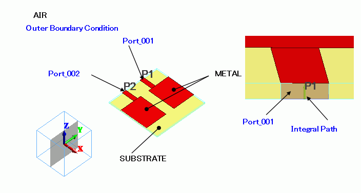
Model
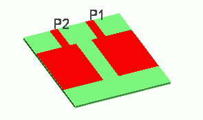
Antenna pattern METAL is a sheet body created on a rectangle substrate SUBSTRATE.
It is covered with spherical air (AIR). Open boundary is set on the surface of AIR.
Body Attributes and Materials
|
Body Number/Type |
Body Attribute Name |
Material Name |
|
1/Sheet |
METAL |
003_Ag |
|
5/Sheet |
METAL |
003_Ag |
|
10/Sheet |
METAL |
003_Ag |
|
15/Solid |
SUBSTRATE |
006_Glass_epoxy |
|
16/Sheet |
METAL |
003_Ag |
|
19/Sheet |
Imprinting body |
|
|
20/Sheet |
Imprinting body |
|
|
24/Solid |
AIR |
000_Air |
* Available from the material DB
Boundary Conditions
|
Boundary Condition Name/Topology |
Tab |
Boundary Condition Type |
Settings |
|
Port_001/Face |
Electric |
Port |
Reference Impedance: Select [Specify] and enter 50 [Ohm]. Number of Modes Number of Precalculated Modes: 5 Number of Modes Used in the Actual 3D Analysis: 1 Select Modes: None |
|
Port_002/Face |
Electric |
Port |
Same as Above. |
|
Outer Boundary Condition |
Electric |
Open Boundary |
|
Results
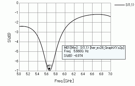
S-parameter S11 is shown below.
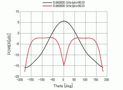
The figure below shows the radiation pattern with the weighed input.
See the Field Superposition Setting for the detail.
|
|
|
MAG |
PHASE [deg] |
|
Red line |
Port_001 |
1.0 |
0.0 |
|
Port_002 |
1.0 |
0.0 |
|
|
Black line |
Port_001 |
1.0 |
0.0 |
|
Port_002 |
1.0 |
180 |
-
See [[Simple Mode] Electromagnetic Waves Directivity] or [[Detailed Mode] Electromagnetic Waves Directivity] for display of radiation patterns.