


|
Home / Technical Notes / Stress Analysis / Contact analysis / How to Avoid Non-Convergence
How to Avoid Non-Convergence
Examine each step's results
Select [Save the results of substeps] on the Step/Thermal Load tab.
You can view each step's results on the results window.
Examine them and find out what to modify
The contact location can be viewed by selecting "Contact force" for field display. See Case 6 below.
Case 1: Deformed contact boundary
If the deformation at the contact boundary is too large, the surface smoothness might be lost.
Further analysis is not possible. Relax some conditions such as load or displacement.

The contact surface is not smooth as in Example 4 of [Examples of Contact Analysis].
Case 2: Sudden change of displacement
If a sudden balance change occurs at a step, the calculation does not converge.
Adjust the conditions or modify the model so that the change is moderated.

With this model, the simulation is possible up to the state when the contact is suddenly released.
Relax the forced displacement condition.
Case 3: Instable balance of forces
If the balance of forces is instable, the direction of deformation is unpredictable and the matrix equation cannot be solved mathematically.
Modify the model or conditions so that the balance shifts stably.

The model in the right is preferred. See Example 6 of [Examples of Contact Analysis].
Case 4: Too many nodes engaged in contact
It is easy to converge if less number of nodes are engaged in contact.
It is hard to converge if the number of engaged nodes is high at the early stage of iterative calculations and low at the final stage.
Modify the conditions so that the contact is made gradually.

ATS (Automatic Time Stepping) is also effective to avoid this kind of non-convergence: Click High-level Setting tab > [Nonlinear analysis] > select ATS (Automatic Time Stepping).
Case 5: Indefinite displacement
Example 7 of [Examples of Contact Analysis]:
Apply proper constraints to prevent indefinite displacement.

Removing the gap between the bodies as shown below is effective as well.

In the upper figure, the boundary condition is changed from load to displacement. In the lower figure, the gap between bodies is removed.
For the displacement boundary condition, the load can be calculated from the external/reactive force and the displacement.
Example 8 of [Examples of Contact Analysis]:

A symmetric half model gives a constraint to the red body,
as the displacement normal to the plane of symmetry is fixed. With this arrangement, the x-direction displacement is no longer indefinite.
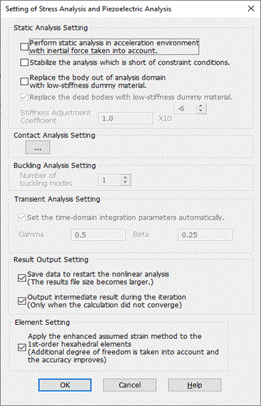
Click [Setting of stress analysis and piezoelectric analysis] on the High-level Setting tab
> select [Stabilize the analysis which is short of constraint conditions]. This will remove the indefinite displacement in z direction.
Case 6: Contactor surface is on the other side of contactee surface.
Example 9 of [Examples of Contact Analysis]:


In this case, it is judged that the contact is made even though it is not.
The left figure indicates the contact location, which is shown with "Contact force" selected as field.
The contact force appears to exist even though there is no contact.
To avoid this, click [Setting of stress analysis and piezoelectric analysis] on the High-level Setting tab,
enter a positive number in Penetration Tolerance.
The number has to be smaller than the distance between contactor and contactee surfaces.
In this example, enter any value between 0 and 1.5.