|
Home / How to Set Body Attribute, Material Property and Boundary Condition / Body Attribute Tabs / Fluid Tab
Fluid Tab
The body attributes relating to fluid are set on this tab.
It is shown in the [Edit Body Attribute] dialog box. See [How to Set Body Attribute/Material Property].
|
Setting Item |
Notes |
|
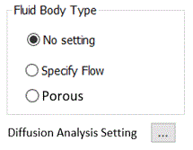
Fluid Body Type |
No setting No particular setting is required for a fluid type.
Specify flow
Sets condition that creates flow inside a body. It is used to give flow inside a body with a fan.
The fluid in the surrounding fluid body flows in from the inflow face to the inside of the body and flows out from the outflow face.
The boundary temperature and the boundary turbulent flow rate are given so that the outflow rate and inflow rate are same.
Porous Medium
Sets fluid resistance by porous body to analyze a domain where the fluid does not flow smoothly.
|
|
Diffusion Analysis Setting |
Sets the initial value of diffusion if diffusion analysis is selected in the analysis condition.
|
|
Inflow face/Outflow face |
Settable if [Specify Flow] is selected for the fluid body type.
Determines the internal flow direction.
|
|
Inlet/Outlet Type |
Settable if [Specify Flow] is selected for the fluid body type.
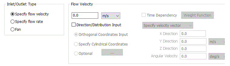
Specify flow velocity Specifies the flow velocity in normal direction to the face. If [Direction/Distribution Input] is set, [Specify direction vector] and [Specify velocity vector] are selectable in addition to velocity.
[Specify direction vector] sets the inflow direction for the specified flow velocity on the orthogonal coordinates or cylindrical coordinates. In this setting, unit vector is not required for the input. Normalization will be executed automatically. [Specify velocity vector] sets the velocity vector directly on the orthogonal coordinates, cylindrical coordinates, or distribution input. In this setting, if cylindrical coordinates are selected, angular velocity with gravity center of the specified face can be specified. See [How to Set Distributed Boundary Condition and Body Attribute] for the detail.
*If the direction vector and the velocity vector are in the outflow direction in relation to the normal vector of the inlet, where the inner product with normal vector is negative, the error message [Failed to create the boundary condition data for the fluid analysis] will show up.
*In the orthogonal coordinates, the vector is specified by X, Y, Z directions of the global coordinates. In the cylindrical coordinates, the vector is specified by the radius direction, the tangential direction, and the axial direction where the axial direction is normal to the face
*In the 2D axisymmetric analysis, setting of direction vector and velocity vector by the cylindrical coordinates is not allowed.
*Direction and direction are reflected on the inflow face side.
*Time dependency setting with the weight function is allowed for the transient analysis. Select Time Dependency and click Weight Function. [Time-Weight] table will appear.
Specify flow rate Specifies the volumetric flow rate in the normal direction to the face. If [Direction/Distribution Input] is set, [Specify direction vector] is selectable in addition to the volumetric flow rate.
[Specify direction vector] sets the inflow direction for the specified volumetric flow rate on the orthogonal coordinates or cylindrical coordinates. In this setting, unit vector is not required for the input. Normalization will be executed automatically.
*If the direction vector and the velocity vector are in the outflow direction in relation to the normal vector of the inlet, where the inner product with normal vector is negative, the error message [Failed to create the boundary condition data for the fluid analysis] will show up.
*In the 2D axisymmetric analysis, setting of direction vector and velocity vector by the cylindrical coordinates is not allowed.
*Direction and direction are reflected on the inflow face side.
* You may set the time dependency with the weight function for transient analysis. Select Time Dependency and click Weight Function. [Time-Weight] table will appear.
Fan Sets the relationship of the volumetric flow rate and the differential pressure (P-Q characteristics) in the table.
|
|
Porous Medium Setting |
Settable if [Porous Medium] is selected for the fluid body type.
Flow Velocity Dependency
There are four methods for the porous medium setting: 1st-order equation, 2nd-order equation, exponentiation, and porosity. See [Porous Medium Setting] for the details of 1st-order equation, 2nd-order equation, and exponentiation.
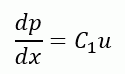
1st Order Equation: Specifies the coefficient where the pressure loss caused by the resistance inside of the porous part is given by the 1st order equation of the flow velocity, u.
dp/dx: pressure loss per distance, p: pressure, u: flow velocity, C1: 1st order coefficient
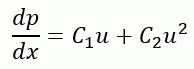
2nd Order Equation: Specifies the coefficient where the pressure loss caused by the resistance inside of the porous part is given by the 2nd order equation of the flow velocity, u.
dp/dx: pressure loss per distance, u: flow velocity, C1: 1st oder coefficient, C2: 2nd order coefficient
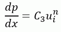
Exponentiation: Specifies the coefficient where the pressure loss caused by the resistance inside of the porous part is given by the exponentiation of the flow velocity, u.
dp/dx: pressure loss per distance, u: flow velocity, C3: exponentiation, n: coefficient of exponentiation:
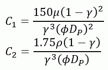
Calculate from porosity: Calculates the 2nd order coefficient automatically from the Ergun equation. Usable when large number of particles are in the air domain.
Ergun Equation
μ: viscosity, ρ: density, γ: porosity, DP: diameter of particle, Φ: shape factor
Porosity
Porosity: Sets porosity. The physical property of the inside of porous part is corrected to solve the diffusion in the fluid-thermal analysis.
Particle diameter and Shape factor: Calculates coefficient of the 2nd order equation if [Calculate from Porosity] is selected for the flow velocity dependency. If shape factor is specified, the entered particle diameter will be corrected. The shape factor is an indicator of how close a shape is to sphere. 1 is for sphere and a number less than 1 is for non-sphere.
If volume and surface area of a particle are known, the particle diameter and the shape factor can be calculated with a following file. [Calculation of particle diameter and shape factor]
Material of Solid: selects material from the material list. Calculates the physical property of the inside of porous part with correction for the fluid-thermal analysis.
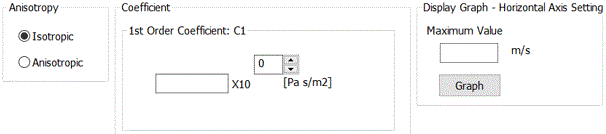
Anisotropy:
Selects Anisotropic if the coefficient is anisotropic.
Coefficient:
Specifies coefficient. Specifies the coefficients in three directions to set the anisotropy.
1st order equation: Set the 1st order coefficient
2nd order equation: Sets the 1st order coefficient C1 and the 2nd order coefficient C2
Exponentiation: Sets the coefficients of exponent C3 and n
Display Graph - Horizontal Axis Setting Specifies the maximum value of the horizontal axis to confirm the flow velocity and the pressure loss.
|
 opens [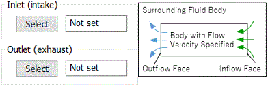
 selects inflow and outflow faces in the modeling window.