


|
Home / How to Set Analysis Condition / List of Analysis Condition Tabs / Magnetic-Stress Analysis Tab
Magnetic-Stress Analysis Tab
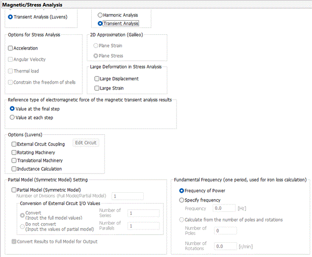
Analysis conditions for the magnetic field-mechanical stress coupled analysis are set on this tab. The solvers are Gauss and Galileo.
It is in the [Analysis Condition Setting] dialog box. See also [How to Set Analysis Condition].
|
Setting Item |
Notes |
|
Magnetic Analysis Type |
Static analysis The constant load, voltage or current is applied.
Harmonic analysis The sinusoidal load, voltage or current is applied.
Transient Analysis Transient states are analyzed. (Note) The magnetic transient analysis is available in an optional package.
|
|
Stress Analysis Type |
Static analysis A certain constant load is applied.
Harmonic analysis The sinusoidal load is applied.
Transient Analysis Transient states are analyzed. The stress-transient analysis is available in an optional package.
|
Analysis Options (Magnetostatic Analysis and Magnetic-Harmonic analysis)
|
Analysis Options |
Notes |
|
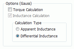
Calculate Torque |
Calculates the torque of the electromagnetic force. Available for the 2D or 3D static analysis. |
|
Calculate Inductance |
Calculates the self-inductance, mutual inductance, and impedance(in the harmonic analysis only).
|
|
Calculation Type |
Select a calculation type of inductance from the following.
Apparent Inductance Differential Inductance
Selection is required if the analysis type is static as well as nonlinear. For other analysis types, the setting is irrelevant. The results will be the same whichever is opted.
See [Calculation Type of Inductance] for details.
|
Options (Magnetic Transient Analysis)
|
Analysis Options |
Notes |
||||||||||
|
External Circuit Coupling |
Executes a coupled analysis with the external circuit.
Click
|
||||||||||
|
Rotating Machinery |
Analyzes rotating machinery such as motor and generator. Refer to [Rotating machinery tab] for detailed setting. |
||||||||||
|
Calculate the Inductance |
Calculates the self-inductance and mutual inductance.
|
||||||||||
|
Partial Model (Symmetric Model) Setting |
Sets the partial model (symmetric model). Setting items are as follows.
Partial Model (Symmetric Model) Selected if the analysis domain is partial model (symmetric model) such as period symmetric. Number of Divisions (Full model/Partial model) Sets the number of divisions of the full model. If the the model is quarter symmetric, enter 4. Conversion of I/O values of External Circuit If [Convert] and [Convert results to full model for output] are selected, the values related to the external circuit will be converted to the full model for output. Converted values are such as current of components of the circuit, which are displayed on the results table. If [Convert] is selected, enter the number in[Number of series] and [Number of parallels] for coils on the external circuit. See [Example of External Circuit Conversion Setup] for the details. See also [External Circuit Conversion]. Convert Results to Full Model for Output Converts the results (values such as torque which are shown in the result table) to the full model for output. In the case of 2D quarter symmetric model for example, the torque value is obtained by [torque value of the quarter model x model thickness x number of divisions of the full model].
|
||||||||||
|
Fundamental Frequency (for determining one period and iron loss calculation) |
Used to determine one period of the electric angle and calculate the iron loss. Available only for the transient analysis.
Frequency of Power Automatically referred to. Not available for the DC power. It is determined by the setting on the [Current] tab in the body attribute.
The fundamental frequency is specified manually.
Calculate from the number of poles and rotations The number of poles and rotations of the rotating machinery are used for calculation. Enter the number of poles. The number of rotations on the [Rotating Machinery] tab is referred to.
|
 and launch
 Options (Stress Analysis)
|
Analysis Options |
Notes |
|
Acceleration |
Takes the weight of the model into account. Not selectable in the resonant analysis.
|
|
Angular velocity |
Takes the centrifugal force into account. Available for the axisymmetric or 3D static analysis. Yes, it is possible. The rotation axis is fixed to Z. |
|
Thermal Load |
Takes the thermal load into account. If selected, the thermal load can be set on the Step/ thermal load tab.
|
|
Constrain the Freedom of Shells |
Available for the 3D analysis. If selected, the freedom of displacement in the rotational direction can be constrained on the mechanical tab. If selected, the freedom of displacement in the rotational direction is constrained on the mechanical tab.
|
|
2D Approximation |
To perform the 2D analysis, select either one below. Plane Strain If the object is fixed in the Y direction, there will be no displacement in the Y direction. The X/Z components of the strain are only taken into account. This is called the planar strain approximation. Plane Stress If the object's Y dimension is considerably smaller than the X/Z dimensions and the object can deform freely in the Y direction, it can be assumed that the stress has X/Z components only. This is called the plane stress approximation.
|
|
Large Deformation |
Analyzes the geometric nonlinearity involving large deformation. Large deformation involves rotation and large strain of the elements. For the details, see Analysis of Large Deformation (Geometric Nonlinearity) in the Technical Note. - Select "Large displacement" to have rotation involved. The total Lagrangian formulation with Green-Lagrangian strains is used. - Select both "Large displacement" and "Large strain" to have rotation and large strain involved. The updated Lagrangian formulation with logarithmic strain is used. It is recommended to select "Large displacement" when you are selecting "Large strain". - Select "Large strain" to have large strain involved. The updated Lagrangian formulation with logarithmic strain is used. Executes iterative calculations that may take long time. Available for the static analysis only.
|
|
Reference type of electromagnetic force of the magnetic transient analysis results |
In the transient analysis, select a type from the following.
Value at the final step The electromagnetic force in the final timestep of the magnetic analysis is referred to as the load in the stress analysis. The load is constant over the time.
Value at each step Selectable for the stress-transient analysis. The electromagnetic force in each timestep of the magnetic analysis is referred to as the load in each timestep of the stress analysis.
|
The Relating Tabs
The relating tabs are [External Magnetic Field] tab,[Open Boundary] tab, [Harmonic Analysis] tab, [Torque Calculation] tan, [Rotating Machinery] tab, [Resonant Analysis] tab, [Harmonic Analysis] tab, [Transient Analysis] tab, [Step/Thermal Load] tab, [Acceleration] tab, [Angular Velocity] tab, and [High-Level Setting] tab.
How to Modify Analysis Conditions
To modify the analysis conditions, go to [Model] tab
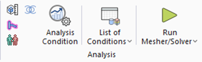
and click [Analysis Condition]  . The dialog box will appear.