Home / Tutorial / Electric Analysis (Coulomb) / 06.Set the Boundary Conditions
06.Set the Boundary Conditions
Set the boundary conditions to the electrodes.
You need to set boundary conditions on some parts of model's body (topology).
It varies depending on the analysis.
The boundary conditions are distinguished by name. It is not allowed to assign the same name to the different boundary conditions
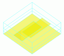
Procedure
-
On the [Model] tab, go to
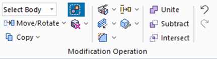
and click Select Face on the drop-down list at  . .
|
|
-
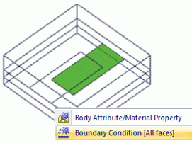
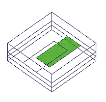
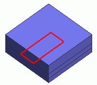
Highlight the rectangle on the top face of Sub2 and click to select.
|
|
-
Right-click to open the menu, and select [Boundary Condition].
|
|
-
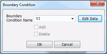
In the [Boundary Condition] dialog box,
enter Boundary Condition Name: V1
and click  . .
-
Any name is acceptable.
|
|
-
In the [Edit Boundary Condition] dialog box,
go to the [Electric] tab,
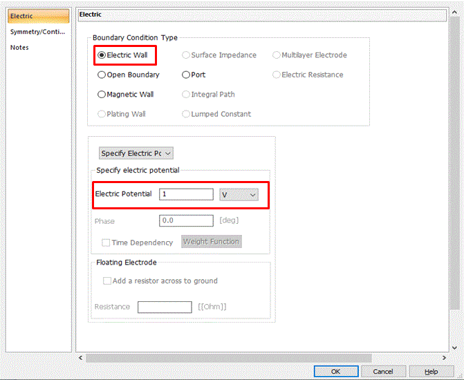
set Boundary Condition Type: Electric Wall,
and set Electric Potential: 1 [V]
and click  . .
Then click to exit the [Boundary Condition] dialog box.
|
|
-
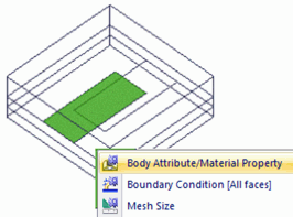
Highlight the rectangle on the top face of Sub1 and click to select.
|
|
-
On the right-click menu, click [Boundary Condition].
|
|
-
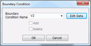
On the [Boundary Condition] dialog,
enter Boundary Condition Name: V2
and click .
|
|
-
In the [Edit Boundary Condition] dialog box,
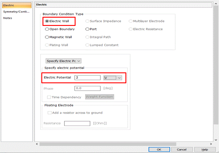
set Boundary Condition Type: Electric Wall,
set Electric Potential: 2 [V]
and click .
Then click to exit the [Boundary Condition] dialog box.
|
|
-
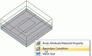
Let's set the grounding.
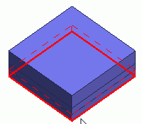
Highlight the bottom face of the model and click to select.
|
|
-
On the right-click menu, click [Boundary Condition].
|
|
-
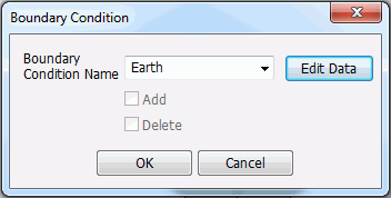
In the [Boundary Condition] dialog box,
enter Boundary Condition Name: Earth
and click .
-
Any name is acceptable.
|
|
-
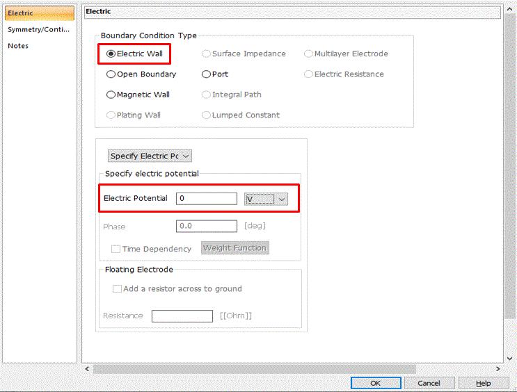
In the [Edit Boundary Condition] dialog box,
on the [Electric] tab,
select Electric Wall in the Boundary Condition Type tab and
enter Electric Potential: 0 [V] and
click .
Then click to exit the [Boundary Condition] dialog box.
|
|
|
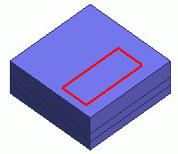
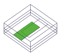
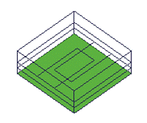
The boundary conditions have been set. |
This figure is shown in wireframe. |



 Prev Next