


|
Home / How to Set Analysis Condition / Electromagnetic Analysis [Hertz] / Hertz Option
Options for Electromagnetic Analysis
This dialog box appears when the Options button for an electromagnetic analysis is pressed in the Analysis Condition Setting dialog box.
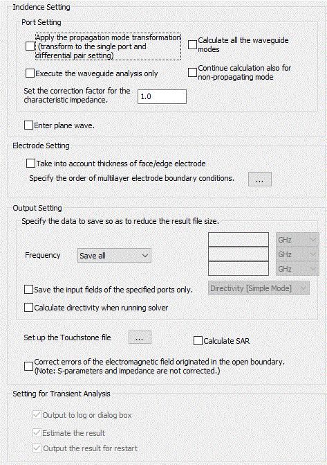
Incidence Setting
|
Options |
Notes |
|
Execute the waveguide analysis only |
Selectable for 3D harmonic analysis. In Hertz 3D harmonic analysis, the waveguide analysis is performed first of all to obtain the propagation modes. Then the electromagnetic field is calculated. If this option is selected, you can check whether the expected propagation modes are obtained on the results window.
|
|
Calculate all the waveguide modes |
Selectable for 2D waveguide analysis and 3D harmonic analysis. This option helps the waveguide calculation converge. However the calculation time will be longer as all the modes are calculated especially if there are a number of elements.
|
|
Apply propagation mode transformation |
|
|
Correction Factor for Characteristic Impedance |
Adjusts the characteristic impedance acquired in Hertz 3D harmonic analysis with this factor. Applicable for the symmetric model. |
|
Incident wave (plane wave) |
If this option is selected, the plane waves specified on the incident wave tab can be input.
|
|
Continue calculation also for non-propagating mode |
Deselected by default. If the non-propagating mode is selected, the calculation is terminated as an error. If this option is selected, the calculation continues also for the non-propagating mode. |
Electrode Setting
|
Options |
Notes |
|
Take thickness of face/edge electrode into account |
Specifies whether or not the influence of face/edge electrode thickness is taken into account. The face/edge electrode is also called the thin electrode element.
- In the case of 3D harmonic analysis If deselected, the thickness of the plane electrode is ignored.
- In the case of 3D resonant analysis Same as 3D harmonic analysis. Note that "Calculate the Q factor with high accuracy" must be selected
- In the case of 2D waveguide analysis solving the propagation constants If this option is deselected, the thickness of the edge electrodes is ignored.
- In the case of other analyses: 2D/Axisymmetric resonant analysis and 2D waveguide analysis solving frequencies
|
|
Specify the layer order of multilayer electrode boundary condition |
Click this button |
 . The
. The
Output Setting
|
Options |
Notes |
|
Field Data to Save |
[Frequency] Selectable for harmonic analysis.
Save all : All the field data is saved for all the frequencies. If "Don't save" is selected at [Port], however, no field data will be saved.
Don't save: No field data is saved for any frequencies.
Reference freq only: Of all the sweep frequencies specified on the harmonic analysis tab, the field data of the one closest to the reference frequency is saved.
Specified freq only: Enter the frequency. Of all the sweep frequencies specified on the harmonic analysis tab, the field data of the one closest to the entered frequency is saved.
Specify three freqs: Enter three frequencies on the right. Of all the sweep frequencies specified on the harmonic analysis tab, the field data of the one closest to the entered frequency is saved. The field data of fewer than three frequencies may be saved depending on the frequencies specified on the harmonic analysis tab.
|
|
[Save input field of specified ports only] If selected, the electromagnetic field to save is controlled by input port. Port for saving electromagnetic field is specified by selecting "Save the field with the power input at this port" in the Port Setting.
|
|
|
[Calculate directivity when running solver] After selected, select either [Directivity [Detailed Mode]], [Directivity [Simple Mode]], or [Surrounding Electromagnetic Field] from the right submenu. The submenu corresponds to each tab in the analysis condition setting dialog box. By selecting one of the options, you can access and enter data on the corresponding tab. It will allow you to calculate directivity when running solver. The maximum and average values, and efficiency of the specified directivity will be displayed on the result table. And the graph data will be saved in a result folder. Directivity can be calculated for the frequencies at which the field data are saved. The result outputs of directivity are described in detail below. 1. Select [Directivity [[Simple Mode]]. Directivity Graph: Don't save Result Table: Radiation Gain [DBi] (Max, Ave), Total Efficiency 2. Select [Directivity [[Detailed Mode]]. Directivity Graph: Result folder/Analysis model_HERTZ_RAD_PTN.plt Result Table: Radiation Gain [DBi] (Max, Ave), Efficiency, Depending on the selections of the dialog box. 3. Select [Surrounding Electromagnetic Field]. Directivity Graph: Result folder/Analysis model_HELTZ_SEH_FIELD.plt Result Table: Surrounding Electromagnetic Field (Max, Ave), Efficiency, Depending on the selections of the dialog box. Note 1: [Enable each port's individual weight setting for superposed fields display] must be selected on the harmonic analysis tab. Note 2: Select either [Discrete Sweep] or [Parallel Discrete Sweep] on the harmonic analysis tab.
|
|
|
Calculate SAR |
Selectable when the analysis type is [Harmonic analysis]. If selected, the density can be entered for the material property. |
|
Set up the Touchstone file |
Selectable for harmonic analysis. Click this button |
|
Correct errors of the electromagnetic field originated in the open boundary |
Deselected by default. If selected, the electromagnetic field is corrected. The body for correction must be selected too on the Analysis Domain tab. For how to examine the results, see the function of "Correct errors of the electromagnetic field originated in the open boundary" in Example 37: Electromagnetic Field Correction. |
Setting for Transient Analysis
|
Analysis Options |
Notes |
|
Output to log or dialog box |
In the electromagnetic-transient analysis, the output values in each timestep are displayed in the dialog box of convergence status. The output values are voltage, current, TDR, and ratio of residual fields. and the calculation time will be saved to some extent.
|
|
Estimate the result |
When [Input at each port] is selected on the Electromagnetic analysis tab, if the ratio of residual field is greater than the threshold,
|
|
Output the result for restart |
The data of the last timestep is output for restart. If this option is selected, the result data for restart is output even if the field output is not selected on the transient analysis tab. If this option is not selected, the size of the result data can be reduced. |