A central part of flow path, inlet, and outlet are created.
-
On the [Model] tab, go to 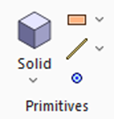 , click [Solid], and select [ [Specify Length]] , click [Solid], and select [ [Specify Length]]  on the submenu. on the submenu.
|
|
|
-
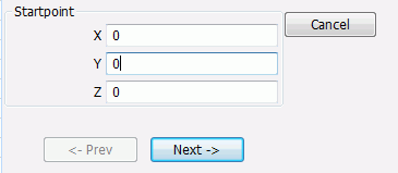
Designate the startpoint., enter Startpoint (X: 0, Y: 0, Z: 0) and click  . .
-
Tips on the parameter input dialog box
If the input value is nil, you don't need to enter 0 in the entry field. The blank is acceptable.
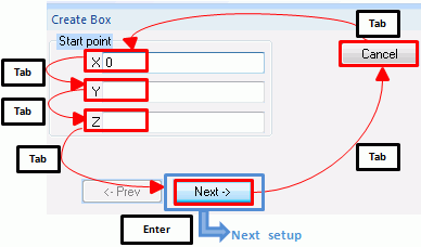
Press the <Tab> key to hop around the items in the dialog box.
Press the <Enter> key on to proceed to the next setting.
|
|
|
-
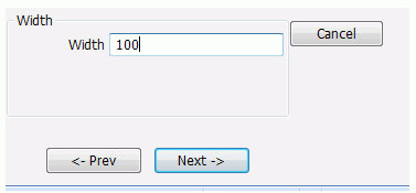
Set the width.
Enter Width: 100 and click .
|
|
|
-
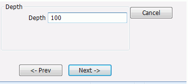
Set the depth.
Enter Depth: 100 and click .
|
|
-
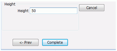
Set the height.
Enter Height: 50 and click  . .
|
|
-
Click  in the parameter input dialog box and exit. in the parameter input dialog box and exit.
-
It is also possible to exit with the <Esc> key.
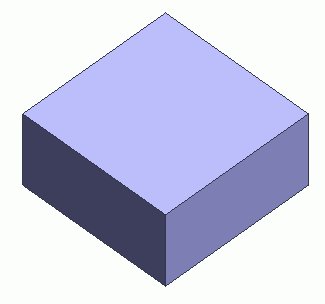
A central part of the flow path has been created.
-
To fit the model on the modeling window, go to the [Model] tab,
and click [Fit]  on on  . .
See [Viewpoint Operation] for the details.
|
|
-
Create another box.
On the [Model] tab,go to , click [Solid], and select [ [Specify Length]] on the submenu.
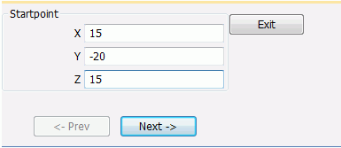
In the parameter input dialog box, enter Startpoint (X: 15, Y: -20, Z: 15) and click .
|
|
-
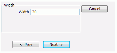
Set the width.
Enter Width: 20 and click .
|
|
-
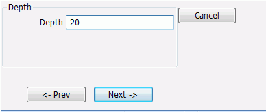
Set the depth.
Enter Depth: 20 and click .
|
|
-
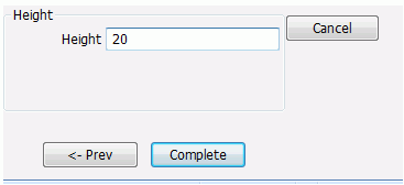
Set the height.
Enter Height: 20 and click .
The inlet (box) has been created.
|
|
- Create another box.
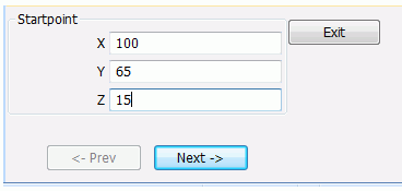
On the [Model] tab,go to , click [Solid], and select [Box [Specify Length]] on the submenu.
In the parameter input dialog box, enter Startpoint (X: 100, Y: 65, Z: 15) and click
|
|
-
Set the width.
Enter Width: 20 and click .
|
|
-
Set the depth.
Enter Depth: 20 and click .
|
|
-
Set the height.
Enter Height: 20 and click .
The inlet (box) has been created.
|
|
-
Click in the parameter input dialog box and exit.
-
It is also possible to exit with the <Esc> key.
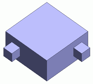
The inlet (box) and outlet (box) have been created. |
|
-
You can undo or redo the operation. The operations can be changed as follows;
In the 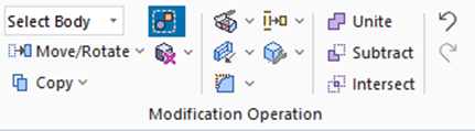
click [Undo]  to undo the modeling or attribute operation. to undo the modeling or attribute operation.
click [Redo]  to redo the modeling or attribute operation. to redo the modeling or attribute operation.
|
|


 Prev Next