CAE Software【Femtet】Murata Software Co., Ltd.

Example49 Fatigue Life Assessment for Solder Ball
-
In this exercise, the fatigue life of a solder ball is evaluated in the multi-step thermal load analysis. The solder is treated as a temperature-dependent elasto-plastic creep material.
will be used in this exercise.
-
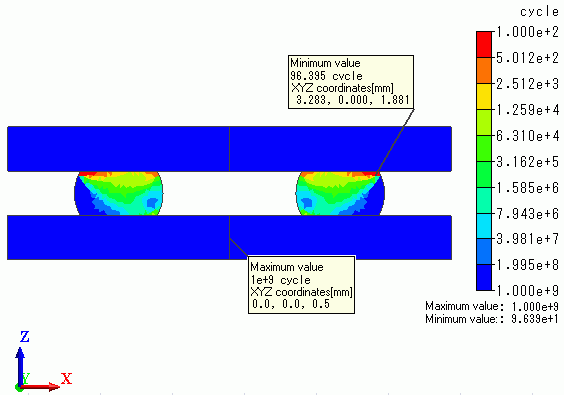
The distributions of equivalent inelastic strain amplitude and fatigue life are solved. The fatigue life is calculated with Manson-Coffin law.
-
Unless specified in the list below, the default conditions will be applied.
Analysis Space
|
Item |
Settings |
|
Analysis Space |
2D |
|
Model unit |
mm |
Analysis Conditions
To simplify the analysis, the 2-D model is analyzed.
Select thermal load option.
|
Item |
Settings |
|
Solvers |
Mechanical Stress Analysis [Galileo] |
|
Analysis Type |
Static analysis |
|
Options |
Select Thermal load. |
The Step/Thermal Load tab is set as follows.
|
Tab |
Setting Item |
Settings |
|||||||||||||||||||||||||||||||||||
|
Step/Thermal Load |
Step Setting |
Multi-step thermal load analysis |
|||||||||||||||||||||||||||||||||||
|
Time Setting |
Set up |
||||||||||||||||||||||||||||||||||||
|
Reference temperature |
25[deg] |
||||||||||||||||||||||||||||||||||||
|
Step/Reached Temperature Setting |
|
||||||||||||||||||||||||||||||||||||
|
Options for the Multi-Step Analysis |
Save the results of substeps: Deselect Fatigue Life Assessment : Select |
The reference temperature (non-stress temperature) is 25[deg]
Select [Multi-step thermal analysis] for the Step Setting, [Set up] for the Time Setting.
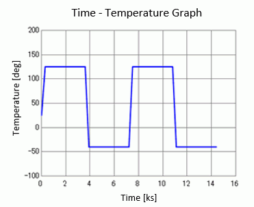
Also, set up in the [Step/Reached Temperature Setting].
The duration of the temperature-rise/fall steps is 300[s] = 5[min] each and the number of substeps is 10.
The duration of the temperature-keep steps is 3300[s] = 55[min] and the number of substeps is 10.
The absolute time is a physical parameter required for the creep materials analysis.
The creep strain changes even during the temperature-keep steps.
The number of substeps is set to 10, the same number as the temperature-rise/fall steps.
“Save results of substeps” is not selected as they are not needed.
The fatigue life assessment settings are set as below.
|
Item |
Settings |
|
Standard Step |
4 |
|
Final Step |
8 |
The thermal cycle of Step 5 (the next step of the standard step) through Step 8 (the final step) is applied repeatedly.
C and n, which are Manson-Coffin law’s coefficients, are set to 1000 and -2 respectively.
Model
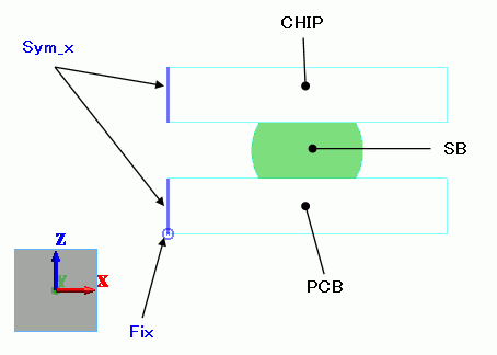
The model is the same as Exercise 35: The Thermally Loaded Elasto-Plastic Bilinear Material.
A silicon chip is to be soldered on a glass-epoxy PCB.
Select [Reflective] on the Symmetry/Continuity tab for the face of symmetry.
The mesh size of the solder ball is set to 0.1.
Body Attributes and Materials
|
Body Number/Type |
Body Attribute Name |
Material Name |
|
0/Sheet |
PCB |
006_Glass_epoxy |
|
1/Sheet |
CHIP |
301_Silicon(single-crystal) |
|
3/Sheet |
SB |
107_Lead-free_solder_SnAgCu |
The material properties are based on the Material DB.
The lead-free solder, SnAgCu, is a temperature-dependent elasto-plastic creep material. Its material properties are set as follows.
|
Material Name |
Tab |
Properties |
|
107_Lead-free_solder_SnAgCu |
Elasticity |
Material Type: Elasto-plastic/Multilinear Hardening Law: Kinematic hardening Temperature Dependency: Yes |
|
Creep |
Creep Type: Power law Temperature Dependency: Select Units in Creep Equation: Stress [MPa], Time [h] |
Boundary Condition
|
Boundary Condition Name/Topology |
Tab |
Boundary Condition Type |
Settings |
|
Fix/Edge |
Mechanical |
Displacement |
Select the XZ component. UX=0, UZ=0 |
|
Sym_x/Edge |
Symmetry/Continuity |
Symmetry |
Reflective |
Results
The calculated remaining (fatigue) life is shown on the output window as follows.
After evaluating remaining lives of all elements belonging to the model, the shortest life in the model is shown on the output window.

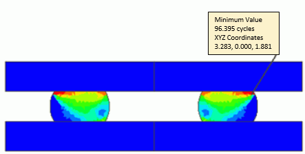
The following diagram shows distribution of equivalent inelastic strain amplitudes. To make this diagram show up, change of the solver type from “structure analysis” to “fatigue life assessment” is needed.
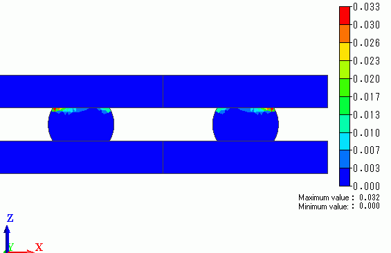
The area contacting “CHIP” exhibits the large inelastic strain.
The following diagram shows the distribution of remaining (fatigue) lives.
Maximum/minimum values and locations are shown as well.
