CAE Software【Femtet】Murata Software Co., Ltd.

Example60 Warp of Substrate in the Cooling Process of Resin
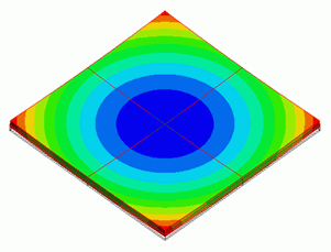
General
-
A warp of alumina substrate coated with epoxy resin is solved in the cooling process of epoxy resin down to 25℃ after hardened at 200℃.
The warp is caused by the different coefficients of expansion between the alumina substrate and epoxy resin. -
Resinous material is used whose physical properties change greatly at the glass transition temperature of 140℃. It is generally recommended to treat such material as viscoelastic material.
In this exercise, the following three models will be compared: 1) viscoelasticity, 2) elasticity, and 3) viscoelasticity (simple setting). -
See [Analysis of Viscoelastic Materials] and [Viscoelasticity (Simple setting)] for more details.
-
The deformation, the displacement and the mechanical stress are solved.
-
Unless specified in the list below, the default conditions will be applied.
Analysis Space
|
Item |
Setting |
|
Analysis Space |
3D |
|
Model Unit |
mm |
Analysis Conditions
The temperature is applied evenly on the model.
Select Thermal load and set the reference temperature and the reached temperature.
There is no need to couple with the thermal analysis [Watt].
|
Item |
Setting |
|
Solver |
Mechanical stress analysis [Galileo] |
|
Analysis Type |
Static analysis |
|
Options |
Select Thermal load. |
For the models 1) viscoelasticity and 3) viscoelasticity (simple setting), Step/Thermal Load tab is set as follows.
Cooling speed is 1℃/s from 200℃ to 25℃. To perform analysis every 5℃, set Time to 175 and Substeps to 35.
|
Tab |
Setting Item |
Setting |
|||||||
|
Step/Thermal Load |
Time Setting |
Set up |
|||||||
|
Reference temperature |
200[deg] |
||||||||
|
Step/Reached Temperature Setting |
|
||||||||
|
Options for the Nonlinear Analysis |
Save the results of substeps : Select |
For the model 3) elasticity, the setting is as follows.
|
Tab |
Setting Item |
Setting |
|||||||
|
Step/Thermal Load |
Step Setting |
Multi-step thermal load analysis |
|||||||
|
Time Setting |
Set up |
||||||||
|
Reference temperature |
200[deg] |
||||||||
|
Step/Reached Temperature Setting |
|
||||||||
|
Options for the Multi-Step Analysis |
Save the results of substeps : Select |
Graphical Objects
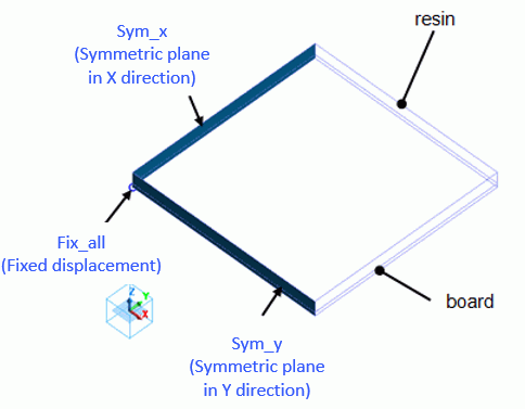
This model consists two boxes for alumina substrate and epoxy resin.
We set the symmetric boundary conditions in X and Y directions.
To solve the amount of warp, displacement of the center is fixed for reference.
Body Attributes and Materials
|
Body Number/Type |
Body Attribute Name |
Material Name |
|
0/Solid |
board |
001_Alumina * |
|
1/Solid |
resin |
1. Viscoelast_Mat |
(*) Available from the Material DB
Material setting is done as follows with the data of dynamic modulus.
See [Converting the Measurement Data of Viscoelastic Materials] for the measurement data of the dynamic modulus.
|
Material Name |
Tab |
Properties |
|
Viscoelast_Mat |
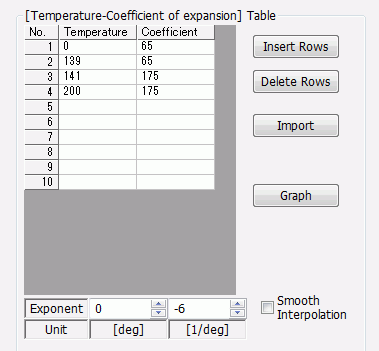
Coefficient of Expansion |
Temperature Dependency: Yes
|
|
Viscoelasticity |
Defined by: Dynamic modulus [temp/freq characteristics] Relaxation Table : Use the csv file below. Viscoelast_Mat.csv |
|
|
Elsat_Mat |
Coefficient of Expansion |
Same as Viscoelast_Mat |
|
Elasticity |
Temperature Dependency: Yes Material Type: Elastic Use the storage modulus measured at 1Hz Elast_Mat.csv |
|
|
SimpleViscoelast_Mat |
Coefficient of Expansion |
Same as Viscoelast_Mat |
|
Elasticity |
Temperature Dependency: Yes Material Type: Viscoelasticity Setting by: Table Poisson’s Ratio: 0.3 Glass Transition Temperature (Tg): 140 [deg] Use the storage modulus measured at 1Hz and csv file below |
Boundary Conditions
Displacement and face of symmetry are set as follows.
|
Boundary Condition Name/Topology |
Tab |
Boundary Condition Type |
Setting |
|
Fix_all/Vertex |
Mechanical |
Displacement |
Select the UX, UY, UZ components |
|
Sym_x/Face |
Symmetry/Continuity |
Symmetry |
Select Reflective |
|
Sym_y/Edge |
Symmetry/Continuity |
Symmetry |
Select Reflective |
Results
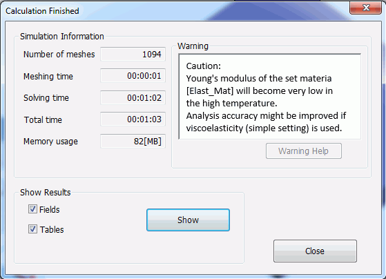
At the end of the analysis of model 2), the warning message will appear as below recommending to use the model 3).
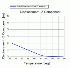
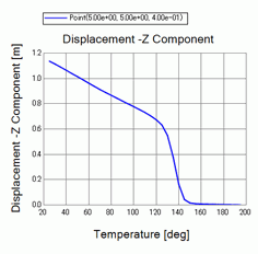
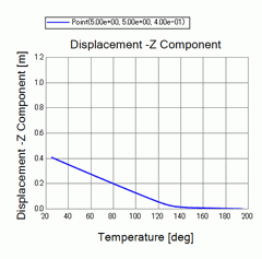
With the following field graph setting, the Z displacements at the tip of substrate are displayed.
Select Horizontal axis: Mode (frequency, time, step, etc) for Type and select Horizontal axis: Temperature.
Coordinates: (5, 5, 0.4)
Mode: 0-34
Results are as follows. The maximum value of the vertical axis is 1.2mm to compare the three models.
| 1) Viscoelasticity | 2) Elasticity | 3) Viscoelasticity (Simple setting) |
|
|
|
|
Comparing models 1) Viscoelasticity and 2) Elasticity, 2) shows larger warp of 1.15mm while 1) is around 0.4mm.
Model 3) Viscoelasticity (Simple setting) shows the same value of 0.4mm as model 1).
If time-dependency data of elasticity is used for analysis, 3) Viscoelasticity (Simple setting) will give accurate results as the warning message above indicates.


