
CAE Software【Femtet】Murata Software Co., Ltd.

Example12 Complex Flows of Forced Convection and Natural Convection
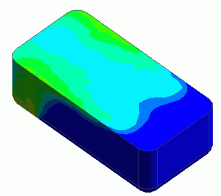
General
-
The flows with different temperatures in the bathtub are analyzed. The water with temperature of 50[deg] is forcibly added to the water of 25[deg].
The complex flows of the forced convection and the natural convection are analyzed with the buoyancy taken into account.
-
The temperature distribution and the flow velocity vectors are displayed.
-
Unless specified in the list below, the default conditions are applied.
Analysis Space
|
Item |
Setting |
|
Analysis Space |
3D |
|
Model Unit |
m |
Analysis Conditions
|
Item |
Setting |
|
Solver |
Fluid analysis [Bernoulli] Thermal analysis [Watt] |
|
Analysis Type |
Fluid analysis: Transient analysis Thermal analysis: Transient analysis |
|
Laminar Flow/Turbulent Flow |
Select Turbulent Flow |
|
Option |
Select Take Buoyancy into Account (Natural Convection) |
|
Layer Mesh Setting for Wall Surface (General Settings) |
Parameters for Automatic Creation Expected Temperature Difference: 25[deg] Select Create the meshes containing pyramid elements if needed |
|
Meshing Setup |
General Mesh size: 0.05 [mm] |
|
Detailed Setting |
Relaxation Coefficient (K, ε) |
|
Tab |
Setting Item |
Setting |
||||||||
|
Transient Analysis |
Table |
|
Model
The water in the bathtub is a solid body.
The inlet and outlet are created. The inflow (forced inflow, flow rate specified) and the outflow (natural outflow) are set. Hot water flows in from the inlet and flows out through the outlet.
The surface of the water is a slip wall assuming it is not constrained by the air

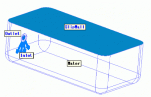
Setting of Body Attributes, Materials, and Mesh Sizes
|
Body Number/Type |
Body Attribute Name |
Material Name |
Mesh Size |
|
0/Solid |
Water |
001_Water * |
0.05 |
* Available from the material DB
Boundary Condition
|
Boundary Condition Name/Topology |
Tab |
Boundary Condition Type |
Setting |
|
Inlet |
Fluid-Thermal |
Inlet |
Inlet Forced Inflow > Specify flow rate 4.0 X 10⁻⁴ [m3/s] Inflow temperature : Direct entry :50[deg] |
|
Outlet |
Fluid-Thermal |
Outlet |
Outlet Natural outflow |
|
SlipWall |
Fluid-Thermal |
Slip Wall |
Slip Wall Layer Mesh Setting Specify for each boundary condition Do not create layer meshes |
Results
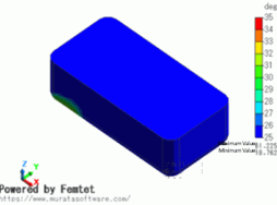
The diagram below shows the temperature distribution.
The range of color scale is between 25[deg] and 35[deg].
The hot water flows along the bottom, reaches the walls, and rises with buoyancy. You can see the high-temperature region is spreading.
The temperature distributions without buoyancy taken into account are shown for reference.
| Buoyancy taken into account (forced convection + natural convection) | Buoyancy not taken into account (forced convection only) | |
| 20[s] |  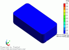 |
  |
| 40[s] |  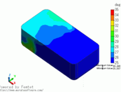 |
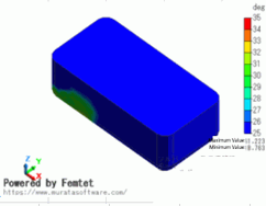  |
| 60[s] |  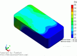 |
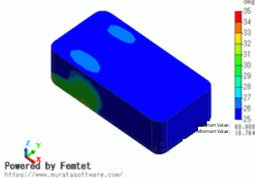  |

