
CAE Software【Femtet】Murata Software Co., Ltd.

Example28 Contact Analysis with Large Deformation
General
-
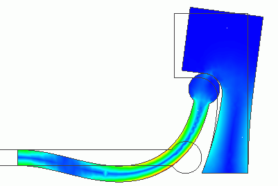
A round-head stick contacts a concave face. The stick exhibits the large deformation.
-
Unless specified in the list below, the default conditions will be applied.
Analysis Space
|
Item |
Settings |
|
Analysis Space |
2D |
|
Model unit |
mm |
Analysis Conditions
“Large displacement” is selected as a type large deformation.
“Large displacement” is more suitable than “Large strain” for this model.
|
Item |
Settings |
|
Solvers |
Mechanical Stress Analysis [Galileo] |
|
Analysis Type |
Static analysis |
|
Large deformation |
Select “Large displacement”. |
The nonlinear analysis is set up on the Step/Thermal Load tab as follows.
Number of substeps is set to 40, which is larger than the default setting of 20 because the stick exhibits a large deformation and the contact point changes drastically.
As Save results of substeps is selected, states at intermediate substeps through the final step will be saved.
|
Tab |
Item |
Settings |
|
Step/Thermal Load |
Step/Reached Temperature Setting |
Substeps of Step 1 : 40 |
|
Options for the Nonlinear Analysis |
Save the results of substeps : Select |
Model
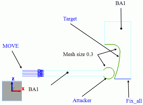
This model consists of two bodies: BA1 and BA2. They have the same body attributes and material properties.
The mesh size of contact surfaces is set to 0.3[mm], which is smaller than general mesh size 0.9[mm].
Body Attributes and Materials
|
Body Number/Type |
Body Attribute Name |
Material Name |
|
2/Sheet |
BA1 |
M1 |
|
7/Sheet |
BA1 |
M1 |
The material properties are set up as follows:
|
Material Name |
Tab |
Properties |
|
M1 |
Elasticity |
Young’s modulus: 1×10^9[Pa] Poisson’s ratio: 0.3 |
Boundary Conditions
On the left end of the stick, the forced displacement of 4.5[mm] is applied in the right direction (positive x direction).
The bottom of the target is fixed completely.
|
Boundary Condition Name/Topology |
Tab |
Boundary Condition Type |
Settings |
|
Fix_x/Edge |
Mechanical |
Displacement |
Select the XZ component. UX=0, UZ=0 |
|
MOVE/Edge |
Mechanical |
Displacement |
Select the XZ component. UX=4.5×10^-3[m] UZ=0x10^-3[m] |
|
Contactor/Edge |
Mechanical |
Contact surface |
Select “Contactor surface”. |
|
Target/Edge |
Mechanical |
Contact surface |
Select “Contactee surface”. |
The contactor and contactee surfaces are designated as a contact pair in the “Boundary Pair” dialog. In contact analyses, the contact surfaces must be designated as a boundary pair.
Results
A deformation diagram of the model with the stress distribution at step 0.2 (equivalent to displacement of 0.9[mm] in X direction of MOVE) is shown below.
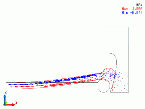
The round head of the stick slides on the concave surface of the target.
A deformation diagram of the model with the stress distribution at step 0.4 (equivalent to displacement of 1.8[mm] in X direction of MOVE) is shown below.
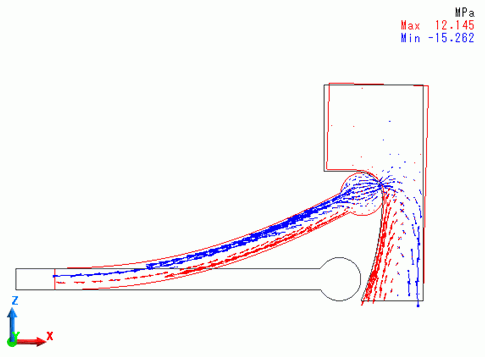
The head reaches the upper end of the concave surface.
A deformation diagram of the model with the stress distribution at step 0.7 (equivalent to displacement of 3.15[mm] in X direction of MOVE) is shown below.
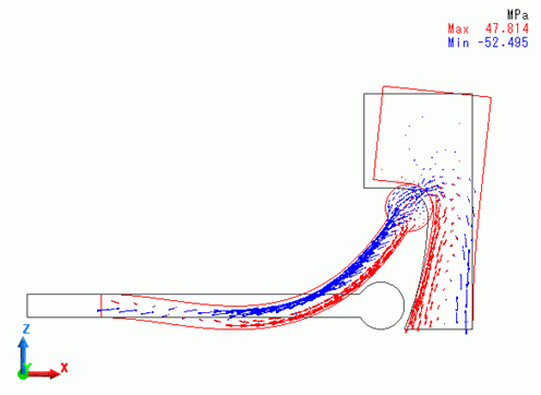
The head starts to rotate. The stick exhibits the large deformation and the target deforms as well.
A deformation diagram of the model with the stress distribution at step 1 (equivalent to displacement of 4.5[mm] in X direction of MOVE) is shown below.
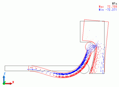
The stick and target body deformed further. Compared with the state at step 0.4, the contact point moved further upward.
On the [Results] tab,

click [Create Animation] ![]() . The animation file (.avi) will be created.
. The animation file (.avi) will be created.

