
CAE Software【Femtet】Murata Software Co., Ltd.
Example29 Contact Analysis of Two Cantilevers
General
-
A cantilever is forced to bend and contacts the other. The deformations are solved three-dimensionally.
-
The lower cantilever is made of elasto-plastic bilinear material. The residual strains and stresses after unloading are solved.
-
Unless specified in the list below, the default conditions will be applied.
Analysis Space
|
Item |
Settings |
|
Analysis Space |
3D |
|
Model unit |
mm |
Analysis Conditions
The model is symmetric over XZ plane, so a half model, cut at XZ plane, is analyzed.
“Large displacement” is selected as a type large deformation.
“Large displacement” is more suitable than “Large strain” for this model.
|
Item |
Settings |
|
Solvers |
Mechanical Stress Analysis [Galileo] |
|
Analysis Type |
Static analysis |
|
Large Deformation |
Select “Large displacement”. |
The nonlinear analysis is set up on the Step/Thermal Load tab as follows.
Number of substeps is set to 40, which is larger than the default setting of 20, because a large deformation is expected.
As Save results of substeps is selected, states at intermediate substeps through the final step will be saved.
Add unloading step is selected as well to analyze the state without forced displacement.
|
Tab |
Setting Item |
Settings |
|
Step/Thermal Load |
Step/Reached Temperature Setting |
Substeps of Step 1 : 40 |
|
Options for the Nonlinear Analysis |
Save the results of substeps : Select Add unloading step : Select |
Model
The bottom face of the upper cantilever and the top face of the lower cantilever are set with the boundary conditions of contactor and contactee respectively.
The side faces on X=0 pane are fixed in all directions, whereas the side faces on Y=0 plane are fixed in Y direction.
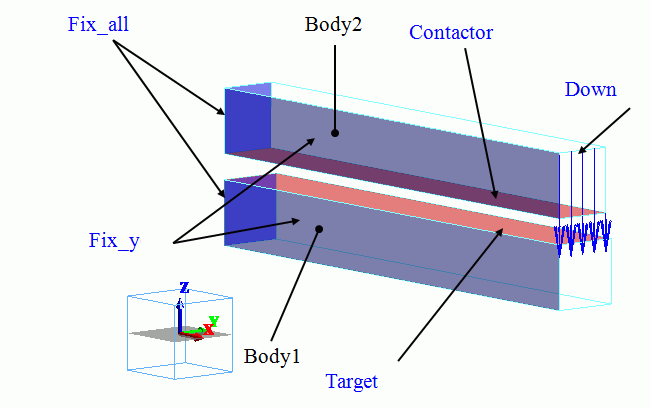
Body Attributes and Materials
|
Body Number/Type |
Body Attribute Name |
Material Name |
|
0/Solid |
Body1 |
Mat1 |
|
1/Solid |
Body2 |
Mat2 |
The material properties are set up as follows:
|
Material Name |
Tab |
Properties |
|
Mat1 |
Elasticity |
Material Type: Elasto-plastic/Bilinear, Isotropic Young’s modulus: 1×10^9[Pa] Poisson’s ratio: 0.3 Strain hardening rate: 0.2×10^9[Pa] Initial yield stress: 8×10^6[Pa] |
|
Mat2 |
Elasticity |
Material Type: Elastic/Isotropic Young’s modulus: 1×10^9[Pa] Poisson’s ratio: 0.3 |
Boundary Conditions
On the left end of the stick, the forced displacement of 4.5[mm] is applied in the right direction (positive x direction).
The bottom of the target is fixed completely.
|
Boundary Condition Name/Topology |
Tab |
Boundary Condition Type |
Settings |
|
Fix_all/Sheet |
Mechanical |
Displacement |
Select all X/Y/Z components. UX=0, UY=0, UZ=0 |
|
Fix_y/Sheet |
Mechanical |
Displacement |
Select the Y component. UY=0 |
|
Down/Edge |
Mechanical |
Displacement |
Select the Z component. UZ=1.5×10^-3[m] |
|
Contactor/Edge |
Mechanical |
Contact surface |
Select “Contactor surface”. |
|
Target/Edge |
Mechanical |
Contact surface |
Select “Contactee surface”. |
The contactor and contactee surfaces are designated as a contact pair in the “Boundary Pair” dialog. In contact analyses, the contact surfaces must be designated as a boundary pair.
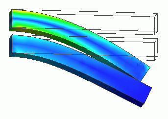
Results
The deformation diagram at step 0.5 (equivalent to Z displacement of -0.75mm for Down) is shown below.
The left figure shows the principal plastic strain. The right figure shows the contour of von Mises equivalent strain.
The upper body is contacting the lower. The plastic strain is exhibited in the lower body.
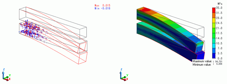
The deformation diagram at step 1 (equivalent to Z displacement of -1.50mm for Down) is shown below.
The left figure shows the principal plastic strain. The right figure shows the contour of von Mises equivalent strain.
The plastic strains are created in the wide area of the lower body. The difference of von Mises equivalent stresses between the two bodies is becoming large.
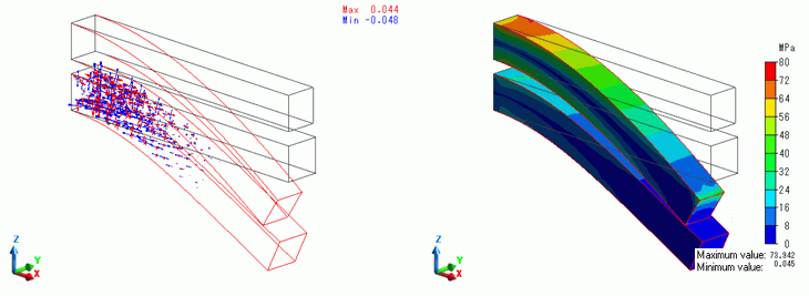
The deformation diagram at step 1.025 which is an unloading stage (1st substep of the unloading stage : No Z displacement for Down) is shown below.
The left figure shows the principal plastic strain. The right figure shows the contour of von Mises equivalent strain.
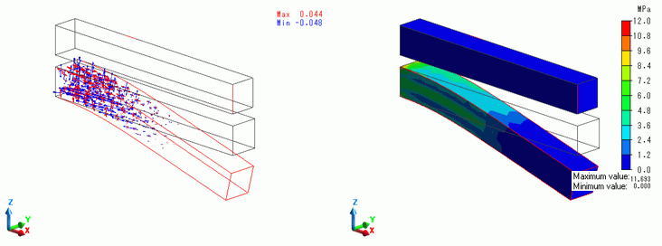
Upper body returns to the original form because it has no Z displacement. Plastic strain remains in the lower body.
The deformation diagram at step 2 which is an unloading stage (last substep of the unloading stage : No Z displacement for Down) is shown below.
The left figure shows the principal plastic strain. The right figure shows the contour of von Mises equivalent strain.
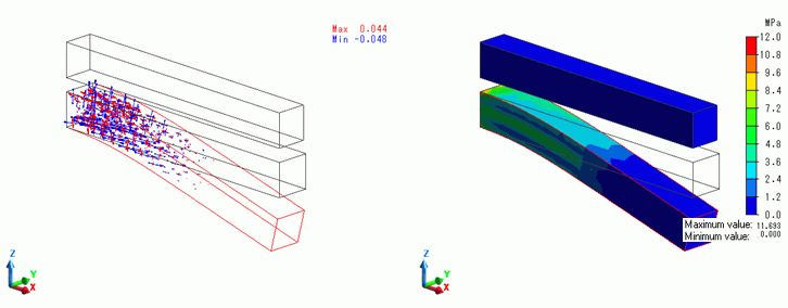
The state is same as step 1.025 with the same results of plastic strain and stress.
On the [Results] tab,

click [Create Animation] ![]() . The animation file (.avi) will be created.
. The animation file (.avi) will be created.