
CAE Software【Femtet】Murata Software Co., Ltd.

Example52 How to View the Mechanical Stress in Arbitrary Direction
General
-
The mechanical stress is displayed in the direction specified in the Set Coordinate System.
-
The deformation, the displacement and the mechanical stress are solved.
-
Unless specified in the list below, the default conditions will be applied.
Analysis Space
|
Item |
Settings |
|
Analysis Space |
3D |
|
Model unit |
mm |
Analysis Conditions
The default conditions are good enough for this exercise.
|
Item |
Settings |
|
Solvers |
Mechanical Stress Analysis [Galileo] |
|
Analysis Type |
Static analysis |
|
Options |
N/A |
Model
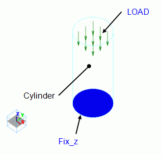
The model is a cylindrical solid body. The material is iron.
Distributed load is applied on the top face. The bottom face is fixedin Z direction.
Body Attributes and Materials
|
Body Number/Type |
Body Attribute Name |
Material Name |
|
0/Solid |
Cylinder |
007_Fe * |
* Available from the Material DB
Boundary Conditions
|
Boundary Condition Name/Topology |
Tab |
Boundary Condition Type |
Settings |
|
Fix_z/Face |
Mechanical |
Displacement |
Select the Z component. |
|
LOAD/Face |
Mechanical |
Distributed face load |
X=0, Y=0, |
Results
The contour indicates the Z normal stress. The unit is [Pa].
The maximum and minimum values for contour are set to 1 and -1 [MPa] respectively in the Graphics Setup dialog box.
To define the Section, enter (0, 0, 2.5) for Point on Cutting Plane and (0, 0, -1) for Normal Vector of Cutting Plane in the Section dialog box.
Also, select “Display the section and the surface simultaneously”.
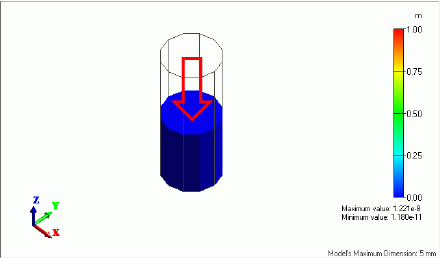
Under this setting, the normal vector matches the direction of the stress component. Therefore, the normal compressive stress is shown.
The loading value, 1[MPa], is the normal compressive stress itself.
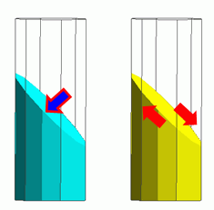
If the section is slanted by 45° (Point on Cutting Plane: X = 0, Y = 0, Z = 2.5、Normal Vector: X = 1, Y = 0, Z = 1), you need to set the coordinate system to see the normal stress on the cutting plane or the shear stress along the cutting plane.
Select [Local Coordinate System] for the Coordinate System Type, and set up as follows.
Origin: X = 0, Y = 0, Z = 2.5, X’ Direction Vector: X = 1, Y = 0, Z = -1
By selecting Z’ normal stress, the stress component can be shown which is normal to the section slanted by 45 degrees.
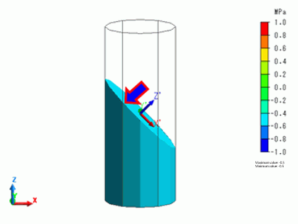
The normal stress is -0.5[MPa].
The value is less than the applied load of -1MPa because it is in the slanted direction to the applied load direction.
By selecting Z’X’ shear stress, the shear stress can be shown along the section slanted by 45 degrees.
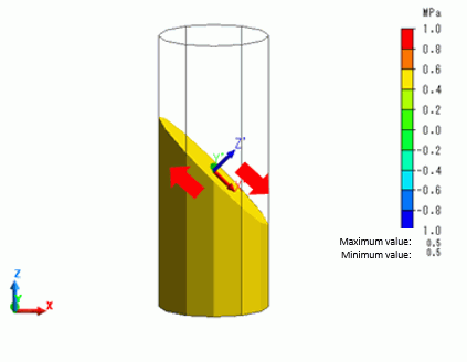
The shear stress is 0.5[MPa].
In the diagram above, the red arrows indicate the force directions causing the shear deformation.

