CAE Software【Femtet】Murata Software Co., Ltd.

Example14 Magnetic Field of Transformer
General
-
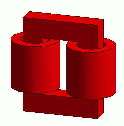
Two coils united by loop magnetic core are solved.
-
The coupling coefficient, the vectors of the magnetic field and the magnetic flux density are solved.
-
Unless specified in the list below, the default conditions will be applied.
Analysis Space
|
Item |
Settings |
|
Analysis Space |
3D |
|
Model unit |
mm |
Analysis Conditions
|
Item |
Settings |
|
Solvers |
Magnetic Field Analysis [Gauss] |
|
Analysis Type |
Static analysis |
|
Options |
N/A |
Model
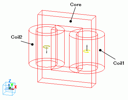
Bodies of two loop coils (Coil1, Coil2) and magnetic core are defined.
The body attributes are set so that the currents of two loop coils flow in the opposite direction each other.
Body Attributes and Materials
|
Body Number/Type |
Body Attribute Name |
Material Name |
|
1/Solid |
Coil2 |
008_Cu * |
|
3/Solid |
Coil1 |
008_Cu * |
|
4/Solid |
Core |
Core |
* Available from the Material DB
The material properties are set up as follows:
|
Material Name |
Tab |
Properties |
|
core |
Permeability |
Relative Permeability 5×10^3 |
Body attribute is set up as follows to apply current to the loop coil.
|
Body Attribute Name |
Tab |
Settings |
|
Coil1 |
Current |
Waveform: Constant Current: 1[A] Turns: 100[Turns] Direction: Loop Coil/Magnetic Field Direction: Magnetic Field Vector: X=0, Y=0, Z=1 |
|
Coil2 |
Current |
Waveform: Constant Current: 1[A] Turns: 100[Turns] Direction: Loop Coil/Magnetic Field Direction: Magnetic Field Vector: X=0, Y=0, Z=-1 |
Boundary Conditions
No setting.
Results
To see the results of inductance calculation, go to the [Results] tab

click [Table] ![]() .
.
The inductances of the loop coils are output as follows.
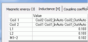
The coupling coefficient is output as follows.
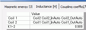
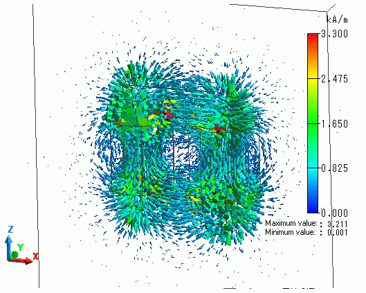
The vectors of the magnetic field are shown below.
The vectors of the magnetic flux density are shown below.
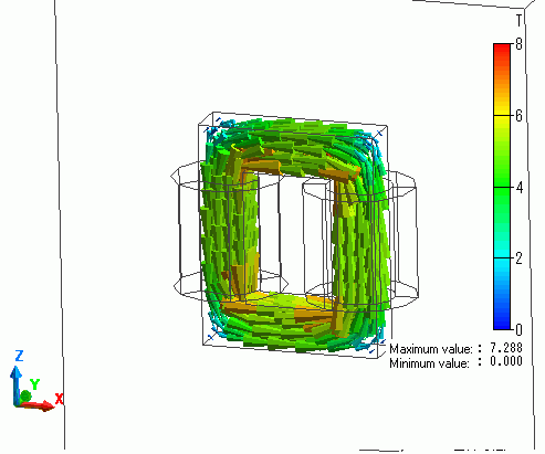
The flux density is looping through the iron core.
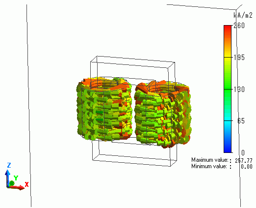
The vectors of the current density are shown below.
