CAE Software【Femtet】Murata Software Co., Ltd.
Example36 Inductor with Superimposed DC (High Frequency)
General
-
The inductance of a high-frequency inductor with superimposed DC is analyzed.
-
The minor-loop permeability is used.
-
This is an harmonic analysis.The high-frequency characteristics such as skin effect are taken into account.
See Exercise 28 for static analysis.
-
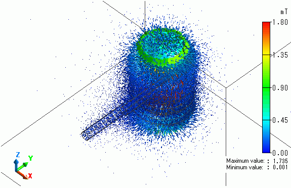
The vectors of the magnetic field and the magnetic flux density are solved.
-
Unless specified in the list below, the default conditions will be applied.
Analysis Space
|
Item |
Settings |
|
Analysis Space |
3D |
|
Model unit |
mm |
Analysis Conditions
|
Item |
Settings |
|
Solvers |
Magnetic Field Analysis [Gauss] |
|
Analysis Type |
Harmonic analysis |
|
Options |
None |
The frequency of the current is set to 1[MHz].
|
Tabs |
Setting Item |
Settings |
|
Mesh |
Frequency-Dependent Meshing |
Reference frequency: 1×10^6[Hz] |
|
Harmonic Analysis |
Sweep Type |
Single frequency |
|
Frequency |
1×10^6[Hz] |
Set the Mesh Tab as follows.
|
Tab |
Setting Item |
Settings |
|
Mesh |
Meshing Setup |
Automatically set the general mesh size: Deselect General mesh size: 2[mm] |
Model
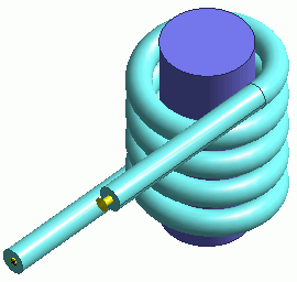
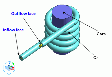
A helical solid body Coil (coil) is defined.
Its inflow/outflow faces are extended to the outside of the ambient air. They contact the electric wall of outer boundary condition.
In the magnetic field harmonic analysis, inflow/outflow faces must be outside of the ambient air. (for the purpose of calculation with FEM)
In this exercise, ambient air is set to be created automatically. Therefore, the inflow/outflow faces are extended to the outside of ambient air.
Body Attributes and Materials
|
Body Number/Type |
Body Attribute Name |
Material Name |
|
0/Solid |
Coil |
008_Cu * |
|
4/Solid |
Coil |
008_Cu * |
|
5/Solid |
Coil |
008_Cu * |
|
6/Solid |
Core |
Core_Nonl_Minor |
* Available from the Material DB
Nonlinear material is defined on the nonlinearity table.
To solve the inductance under DC-biased condition, the magnetic field is solved first with the major loop. It is a static analysis.
Then, by using the minor loop and this magnetic field, the permeability for harmonic analysis is obtained, and the inductance is calculated.
|
Material Name |
Tab |
Setting |
||||||||||||||||||
|
Core_Nonl_Minor |
Permeability |
Magnetization Characteristic Type: Select B-H curve Select “Use the minor-loop permeability” B-H Curve Table
This B-H curve is for DC bias. |
||||||||||||||||||
|
Permeability for Minor Loop |
Magnetization Characteristic Type: Select B-H curve
B-H Curve Table
This B-H curve is for AC operation. |
Body attribute is set up as follows to apply current to the coil.
The value of current set here will be the value of the superimposed DC.
AC current cannot be given. It is assumed to be significantly small compared to DC current.
|
Body Attribute Name |
Tab |
Setting |
|
Coil |
Current |
Waveform: AC Current: 1[A] Turns: 1[Turns] Direction: Specify Inflow/Outflow Faces Select inflow face and outflow face. |
Boundary conditions
No setting.
Results
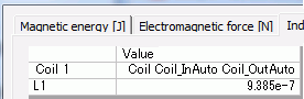
To see the results of inductance calculation, go to the [Results] tab

click [Table] ![]() .
.
The vectors of the magnetic flux density are shown below.