CAE Software【Femtet】Murata Software Co., Ltd.

Example8 View by the Directivity Calculation Method

General
-
View the analysis results by the directivity calculation method.
-
Unless specified in the list below, the default conditions will be applied.
Analysis Space
|
Item |
Settings |
|
Analysis Space |
3D |
|
Model unit |
mm |
Analysis Conditions
|
Item |
Settings |
|
Solver |
Acoustic Analysis [Mach] |
|
Analysis Type |
Static analysis |
|
Options |
N/A |
|
Tab |
Setting Item |
Settings |
|
Harmonic Analysis |
Frequency |
Minimum: 5[KHz] Maximum: 5[KHz] |
Graphical Objects
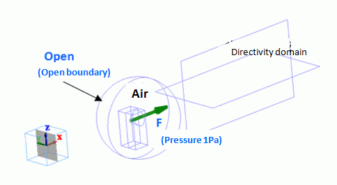
The model is to observe how the speaker’s sound travels for 1-meter distance in the air.
An area is extracted from the spherical ambient air for a speaker’s domain. Therefore, a body of speaker does not exist. The driving source is set at the pressure of 1 [Pa]. For easy viewing of the inside of the model, the open boundary condition is hidden. The directivity domain consists of two sheet bodies.

Body Attributes and Materials
|
Body Number/Type |
Body Attribute Name |
Material Name |
|
2/Solid |
Air |
000_Air(*) |
|
5/Solid |
Air |
000_Air(*) |
|
6/Solid |
Air |
000_Air(*) |
|
9/Sheet |
OUTSIDE |
000_Air(*) |
|
10/Sheet |
OUTSIDE |
000_Air(*) |
* Available from the Material DB
|
Body Attribute Name |
Analysis Domain |
|
OUTSIDE |
Select “Use directivity calculation method” |
-
If “Use directivity calculation method” is selected, such body will be recognized as the domain for the directivity calculation. The material “000_Air” is specified for this body but not used for the calculation. The simulation is performed assuming that the body material with open boundary condition exists in the outside of the boundary.
Boundary Conditions
|
Boundary Condition Name/Topology |
Tab |
Boundary Condition Type |
Settings |
|
F/Face |
Acoustic |
Pressure |
1[Pa] |
|
Open/Face |
Acoustic |
Open boundary |
|
Results
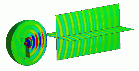
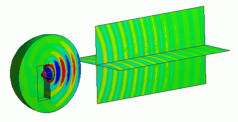
The contour of the directivity domain has been made.
The sound pressure distribution in the wide space can be observed by using the directivity domain.


