CAE Software【Femtet】Murata Software Co., Ltd.

Example10 Size of Analysis Domain and Its Results

General
-
We will study how the different sizes of analysis domain affect the results.
-
The model is based on example 8 of acoustic analysis.
Analysis Space
|
Item |
Setting |
|
Analysis Space |
3D |
|
Model unit |
mm |
Analysis Conditions
|
Item |
Setting |
|
Solver |
Acoustic analysis [Mach] |
|
Analysis Type |
Harmonic analysis |
|
Options |
N/A |
|
Tab |
Setting Item |
Setting |
|
Harmonic Analysis |
Sweep Values |
Minimum: 5[KHz] Maximum: 5[KHz] |
|
Open Boundary |
Type |
Absorbing boundary |
|
Order of Absorbing Boundary |
2nd-order (Models 1 and 2) 1st-order (Model 3) |
Model
We will observe how the speaker’s sound travels in the air and how a model’s form and size affect the results.
A portion is extracted from the spherical or box ambient air for a speaker’s domain. Therefore, a body of speaker does not exist. The driving source is set at the pressure of 1 [Pa]. For easy viewing of the inside of the model, the open boundary condition is hidden. The directivity domain consists of two sheet bodies.
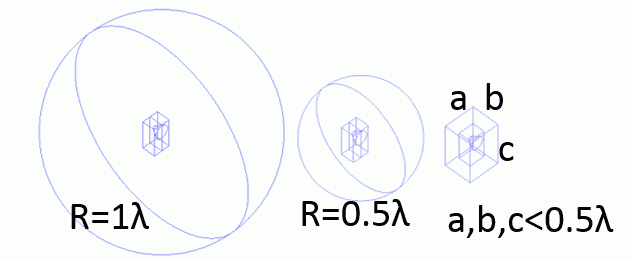
Three models with different forms are analyzed. The models are shown at the top of this page.
Model 1. A speaker is placed in a sphere with radius of one wavelength (60cm). General mesh size is 1/6 of the wavelength.
Model 2. A speaker is placed in a sphere with radius of half wavelength (30cm). General mesh size is 1/6 of the wavelength.
Model 3. A speaker is placed in a box. (The distance from the speaker to the end of ambient air is 5cm.) General mesh size is 1/12 of the wavelength.
Please note that the mesh size of 4 is set to the peripheral faces of the speaker in all three models. It is to calculate correctly the characteristics of the small form of speaker.
Body Attributes and Materials
Models 1 and 2
|
Body Number/Type |
Body Attribute Name |
Material Name |
|
2/Solid |
Air |
000_Air(*) |
|
15/Solid |
Air |
000_Air(*) |
|
18/Solid |
Air |
000_Air(*) |
|
21/Sheet |
OUTSIDE |
000_Air(*) |
|
22/Sheet |
OUTSIDE |
000_Air(*) |
Model 3
|
Body Number/Type |
Body Attribute Name |
Material Name |
|
2/Solid |
Air |
000_Air(*) |
|
14/Solid |
Air |
000_Air(*) |
|
15/Solid |
Air |
000_Air(*) |
|
18/Sheet |
OUTSIDE |
000_Air(*) |
|
19/Sheet |
OUTSIDE |
000_Air(*) |
* Available from the Material DB
|
Body Attribute Name |
|
OUTSIDE |
-
If “Use directivity calculation method” is selected, the body will be recognized as the domain for the directivity calculation. The material “000_Air” is specified for this body but not used for the calculation. The simulation is performed assuming that the body material set with open boundary condition exists in the outside of the boundary.
Boundary Condition
|
Boundary Condition Name/Topology |
Tab |
Boundary Condition Type |
Setting |
|
F/Face |
Sound wave |
Pressure |
1[Pa] |
|
Open/Face |
Sound wave |
Open boundary |
|
Results
The domains of the body attribute names of AIR and OUTSIDE for three models are displayed on the graphs and contour diagrams to see the differences.
There is no difference between three models for the OUTSIDE domain.
The contour diagram of the AIR domain hides half of the domain to show the inside. As you can see from the contour diagram and graph of the AIR domain, three models give almost same results. Only different result is seen near the backside of Model 3.
Sound pressure distribution in the AIR domain Sound pressure distribution in the OUTSIDE domain
Sound pressure distribution in the AIR domain (across A and B) Sound pressure distribution in the OUTSIDE domain (across C and D)
Summary
In Model 3, the distance between the speaker and the open boundary is as short as 1/12 of the wavelength, but the radiation pattern does not show any changes. The mesh size, though, is reduced to about half of Models 1 and 2. It is because the result was shifted when analyzing Model 3 with the same mesh size as Models 1 and 2. Please perform analysis paying attention to this point.

