CAE Software【Femtet】Murata Software Co., Ltd.

Example8 Periodic Structure
-
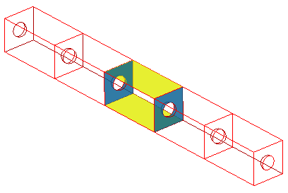
A piezoelectric bar with periodic structure is analyzed. The analysis is done for a base unit extracted from the bar.
-
The periodic boundary condition is set on either face of the base unit.
-
Unless specified in the list below, the default conditions will be applied.
Analysis Space
|
Item |
Settings |
|
Analysis Space |
3D |
|
Model unit |
mm |
Analysis Conditions
|
Item |
Settings |
|
Solver |
Piezoelectric analysis [Galileo] |
|
Analysis Type |
Resonant analysis |
|
Options |
N/A |
|
Tab |
Setting Item |
Settings |
|
Resonant analysis |
Number of modes |
3 |
|
|
Approximated frequency |
0[Hz] |
Model
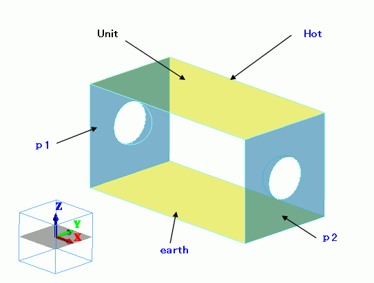
Cut the model with planes of symmetry and set the “periodic” boundary condition on the sections. The top face of UNIT is fixed at 1[V].
The bottom face is fixed at 0[V].
Body Attributes and Materials
|
Body Number/Type |
Body Attribute Name |
Material Name |
|
4/Solid |
UNIT |
000_P-4 * |
* Available from the Material DB
Boundary Conditions
|
Boundary Condition Name/Topology |
Tab |
Boundary Condition Type |
Settings |
|
p1/Face |
Symmetry/Continuity |
Periodic |
|
|
p2/Face |
Symmetry/Continuity |
Periodic |
|
|
hot/Face |
Electric |
Electric wall |
Voltage 1[V] |
|
earth/Face |
Electric |
Electric wall |
Voltage 0[V] |
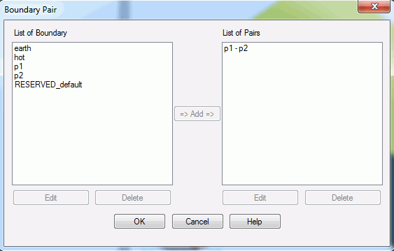
For the periodic boundary conditions, p1 and p2,
On the [Model] tab

click [Boundary Pair] ![]() and register the pair.
and register the pair.
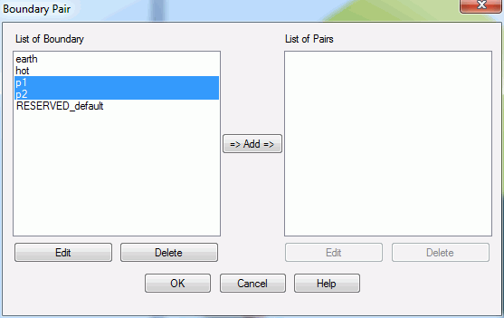
When “Add” is clicked, the dialog box below will appear.
Enter the phase difference of p1 and p2. If in phase, it will be 0[deg]. If completely out of phase, it will be 180[deg].
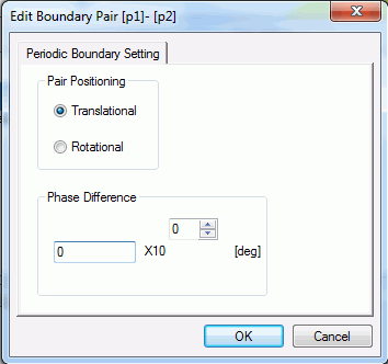
Click OK to finish.
Results
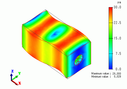
The displacement diagram is shown below. The contour indicates the displacement.
The boundary pair, p1 and p2, are displaced in the same magnitude.
