CAE Software【Femtet】Murata Software Co., Ltd.

Example12 Acoustic Impedance

General
-
Acoustic impedance is set on Exercise 2’s model to see the effect of air resistance.
Analysis Space
|
Item |
Settings |
|
Analysis Space |
3D |
|
Model unit |
mm |
Analysis Conditions
|
Item |
Settings |
|
Solvers |
Piezoelectric Analysis [Rayleigh] |
|
Analysis Type |
Harmonic analysis |
|
Options |
N/A |
The harmonic analysis tab is set up as follows.
|
Tab |
Setting Item |
Settings |
|
Harmonic analysis |
Frequency |
Minimum: 5.6×10^3[Hz] Maximum: 5.7×10^3[Hz] |
|
Step |
Select “Linear step by division number”. Division number: 50 |
Model, Body Attributes and Materials – same as Exercise 2
Boundary Conditions
|
Boundary Condition Name/Topology |
Tab |
Boundary Condition Type |
Settings |
|
Outer Boundary Condition |
Mechanical |
Acoustic Impedance |
409.7[Pa*s/m] |
|
earth/Face |
Electric |
Electric wall |
Voltage specified: Voltage 0[V] |
|
hot/Face |
Electric |
Electric wall |
Voltage specified: Voltage 1[V] |
|
hot/Face |
Mechanical |
Acoustic Impedance |
409.7[Pa*s/m] |
The outer boundary condition and “hot” ad set with the “acoustic impedance” boundary condition.
409.7[Ns/m3] is the acoustic impedance of air.
Results
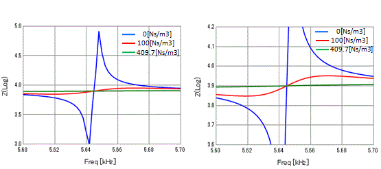
For comparison, the simulation is done for the acoustic impedance of 0[Ns/m3] and 100[Ns/m3] as well as 409.7[Ns/m3].
The frequency characteristics of electric impedance are plotted below.

The right figure is a blow up of the left.
Note that the legends of the series titles are not created by the graphing software.

