
CAE Software【Femtet】Murata Software Co., Ltd.
Example15 External Resister
General
-
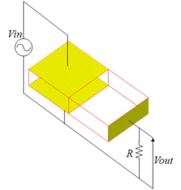
An external resister is connected to a piezoelectric device.
-
The voltage generated across the resister is solved.
-
Unless specified in the list below, the default conditions will be applied.
Analysis Space
|
Item |
Setting |
|
Analysis Space |
3D |
|
Model unit |
mm |
Analysis Conditions
The analysis type is resonant analysis.
|
Item |
Setting |
|
Solver |
Piezoelectric Analysis [Rayleigh] |
|
Analysis Type |
Harmonic Analysis |
|
Options |
N/A |
The harmonic analysis tab is set up as follows.
|
Tab |
Setting Item |
Setting |
|
Harmonic Analysis |
Sweep Values |
Minimum: 200×10^3[Hz] Maximum: 230×10^3[Hz] |
|
Sweep Type |
Division number: 120 |
Graphical Objects
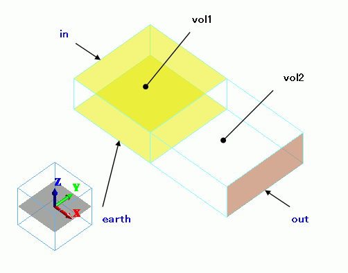
vol1 is polarized in +Z direction, while vol2 is polarized in +X direction.
The top and bottom faces of vol1 are set with electrodes. The voltage is output at an end of vol2.
Body Attributes and Materials
|
Body Number/Type |
Body Attribute Name |
Material Name |
|
0/Solid |
vol1 |
000_P-4 * |
|
1/Solid |
vol2 |
000_P-4 * |
(*) Available from the Material DB
vol1 and vol2 are polarized as follows.
The body attribute directions are set up as follows:
|
Body Attribute Name |
Direction |
|
vol1 |
Specified by: Vector Vector: X=0.0, Y=0.0, Z=1.0 |
|
vol2 |
Specified by: Vector Vector: X=1.0, Y=0.0, Z=0.0 |
Boundary Condition
|
Boundary Condition Name/Topology |
Tab |
Boundary Condition Type |
Setting |
|
earth/Face |
Electric |
Electric wall |
Voltage specified: Voltage 0[V] |
|
in/Face |
Electric |
Electric wall |
Voltage specified: Voltage 1[V] |
|
out/Face |
Electric |
Electric wall |
Floating electrode Select “Add a resistor across to ground”. The resistance is 1, 5 or 10[Mohm]
|
Results
The frequency characteristics of the floating electrode’s voltage is shown below.
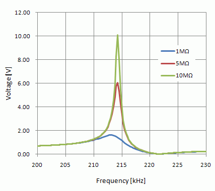
The voltage peaking is less with lower resistance value.