
CAE Software【Femtet】Murata Software Co., Ltd.

Example18 Effect of Tensile Force
General
-
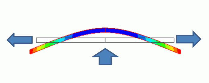
The hardening effect of tensile force is solved. See the figure above. The bar is pulled at both ends and pushed upward from the bottom at the same time. If the pulling force becomes large, deformation due to the pushing force will be small. This effect is taken into account.
-
The material used in this Exercise has no piezoelectricity. Analysis can be accurately performed if the large displacement analysis is used in the mechanical stress analysis. It will, however, require the transient analysis to analyze the vibration. In this Exercise, the function to take the initial stress into account is used which can be applied to the harmonic analysis and resonant analysis. See Analysis with the initial stress taken into account for the details.
-
The result of static analysis is used as an initial stress (tensile force.
-
A half model is analyzed. Analysis procedure is as follows.
Analysis 1: The static load is applied to the bar and the bar is pulled both ends.
Analysis 2: The bar is fixed at both ends and pushed upward from the bottom. The displacement obtained in the Analysis 1 is used to take the initial stress into account. Select [Analysis 1] on the Result Import tab.
Analysis Space (Common to Analyses 1 and 2)
|
Item |
Setting |
|
Analysis Space |
2D |
|
Model unit |
mm |
Analysis Conditions (Analysis 1)
|
Item |
Setting |
|
Solver |
Piezoelectric Analysis [Rayleigh] |
|
Analysis Type |
Static Analysis |
|
Options |
N/A |
Graphical Objects (Analysis 1)
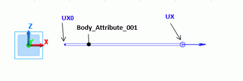
A symmetric half model is analyzed. Symmetric boundary condition is set on the left end. On the right end, 0[mm] is set. It indicates that X component of the displacement is -0.1[mm], and Y and Z components do not move.
Body Attributes and Material Properties Setting (Common to Analyses 1 and 2)
|
Body Number/Type |
Body Attribute Name |
Material Name |
|
0/Sheet Body |
Body_Attribute_001 |
Material_Property_001 |
|
Material Name |
Tab |
|
|
Material_Property_001 |
Piezoelectricity |
Piezoelectricity: No Anisotropy: Isotropic Young’s modulus= 2×10^11[Pa] Poisson’s ratio=0.3 |
Boundary Conditions (Analysis 1)
|
Boundary Condition Name/Topology |
Tab |
Boundary Condition Type |
Setting |
|
UX/Vertex |
Mechanical |
Displacement |
Select all UX/UY/UZ components.
X=-0.1[mm] Y=Z= 0.0[mm]
|
|
UX0/Edge |
Symmetry/Continuity |
|
Symmetry |
Results (Analysis 1)
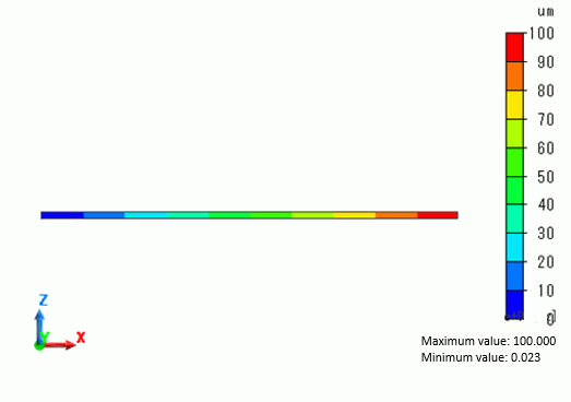
The half model is shown. The bar is fixed at its left end and pulled at the right end. The diagram below is the contour of displacement. The maximum value is 100[um]. This value is equal to that of the displacement in X direction set in the boundary condition.
Analysis Conditions (Analysis 2)
|
Item |
Setting |
|
Solver |
Piezoelectric Analysis [Rayleigh] |
|
Analysis Type |
Static Analysis |
|
Options |
Analysis with the initial stress taken into account Select Take into account. Select Use analysis result (Result import) |
Result Import tab is set as follows.
|
Tab |
Setting Item |
Setting |
|
Result Import |
Specify Result |
For analysis model, |
Graphical Objects (Analysis 2)
As in the Analysis 1, a half model is analyzed. Its shape must be the same because the displacement in the Analysis 1 is used. Symmetric boundary condition is set on the left end as this is a half model.
The shape is the same but the boundary conditions are partially changed. The right end is fixed and lumped load is applied to the left end.

Body Attributes and Material properties Setting (Analysis 2)
Same as Analysis 1.
Boundary Conditions (Analysis 2)
|
Boundary Condition Name/Topology |
Tab |
Boundary Condition Type |
Setting |
|
PUSH/Vertex |
Mechanical |
Lumped vertex load |
X=Y=0.0[N] Z=1.0[N]
|
|
UX/Vertex |
Mechanical |
Displacement |
Select all UX/UY/UZ components. X=Y=Z=0.0[mm]
|
|
UX0/Edge |
Symmetry/Continuity |
|
Symmetry |
Results (Analysis 2)
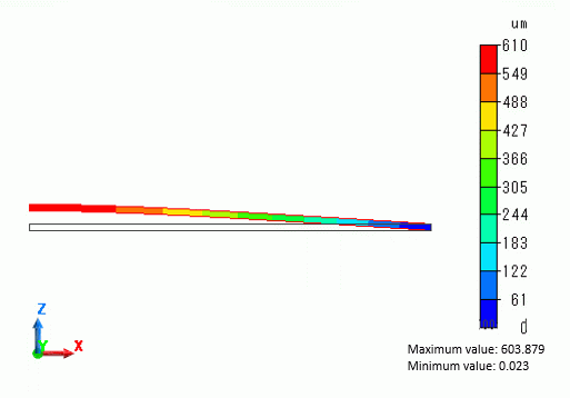
As the right end is fixed and the left end is pushed upward, obtained results are as expected. In the diagram below, however, the effect of tensile force in the Analysis 1 cannot be seen.
By changing the load in the Analysis 1, we will see how it will affect the results of Analysis 2.
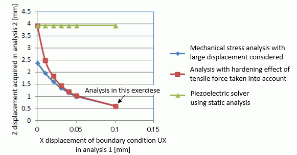
In the diagram above, “Mechanical stress analysis with large displacement considered” can simulate the physical phenomena more accurately than other two analyses. “Piezoelectric solver using static analysis” analyzes X-axis displacement in the Analysis 1 and Z-direction load in the Analysis 2 simultaneously. This analysis does not take into account the effect of tensile force at all.
“Analysis with hardening effect of tensile force taken into account” is the analysis explained in this Exercise. As the tensile force is increased, Z component of displacement comes closer to that of “Mechanical stress analysis with large displacement considered”. This is because the tensile force is assumed to be dominant in the calculation.

