CAE Software【Femtet】Murata Software Co., Ltd.

Example21 Piezoelectric Device with Polarization in Radius Direction

General
-
Voltage is applied to a piezoelectric device with polarization in radius direction.
-
How to set and check the polarization direction will be explained.
-
The deformation, the displacement distribution and the mechanical stress distribution are solved.
Analysis Conditions
|
Item |
Setting |
|
Solver |
Piezoelectric Analysis [Rayleigh] |
|
Analysis Space |
3D |
|
Analysis Type |
Static analysis |
|
Unit |
mm |
|
Options |
N/A |
Model
A model is a solid body. The boundary condition is set on the internal and external faces to specify voltage.
Body Attributes and Materials
|
Body Number/Type |
Body Attribute Name |
Material Name |
|
0/Solid |
Body_Attribute_Name_001 |
000_P-4 * |
* Available from the Material DB
|
Body Attribute Name |
Tab |
Setting |
||||||||||||||||||||||||||||||||||
|
Body_Attribute_Name_001 |
Direction |
Specified by: Vector Select “Use distribution data” |
||||||||||||||||||||||||||||||||||
|
Edit Distribution Data dialog box Distribution Dimension: 2D Coordinate System: Local coordinates Local Coordinates Origin O’: 0.0,0.0,0.0 x10^-3 Vector O’X’: 1.0,0.0,0.0 Vector O’Y’: 0.0,0.0,1.0
|
||||||||||||||||||||||||||||||||||||
|
|
Boundary Condition
|
Boundary Condition Name/Topology |
Tab |
Boundary Condition Type |
Setting |
|
V0/Face |
Electric |
Electric wall |
Voltage specified: Voltage 0[V] |
|
V1/Face |
Electric |
Electric wall |
Voltage specified: Voltage 1[V] |
Results
Direction distribution is examined as follows.
Go to Results tab > Display > Solver > Mesh.
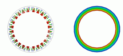
For Field, select Direction distribution. If Element Vector button is pressed, the polarization directions are indicated by arrows as in the below diagram.
As intended, the polarization has been set in the radius direction.
The displacement is examined as follows. Go to Results tab > Display > Solver > Piezoelectric analysis.
By selecting “Displacement” and “Magnitude”, a contour diagram is created as follows. The displacement on the inner area of the ring is larger than the outer area. It indicates the stretch in the circumferential direction and the shrinkage in the thickness direction.
The mechanical stress is examined with a vector diagram. The tensile stress is observed in the outer area and the compression stress in the inner area. The stresses are uniformly applied in the circumferential direction.

