CAE Software【Femtet】Murata Software Co., Ltd.

Example24 Potential Generated by Coriolis Force

General
-
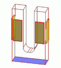
A model in this example is a tuning fork-shaped piezoelectric device to detect the Coriolis force.
The model has piezoelectric driving plates and those to detect angular velocity.
-
A displacement diagram of the piezoelectric device and analysis results of potential of the detecting electrodes are shown below.
-
Unless specified in the list below, the default conditions will be applied.
Analysis Condition
|
Item |
Setting |
|
Solver |
Piezoelectric analysis [Rayleigh] |
|
Analysis Space |
3D |
|
Analysis Type |
Harmonic analysis |
|
Unit |
mm |
|
Options |
Angular velocity |
The harmonic analysis tab is set up as follows.
The angular velocity tab is also set up as follows.
|
Tab |
Setting Item |
Setting |
|
Harmonic Analysis
|
Sweep Values |
Minimum: 8000[Hz] Maximum: 8000[Hz] |
|
Sweep Type |
Select “Linear step by division number”. Division number: 0 |
|
|
Sweep Setting |
Select fast sweep. Tolerance: 1.0×10^-2 |
|
|
Angular Velocity |
Angular velocity |
X = Y = 0, Z = 10[deg/s] |
Model
The driving elements piezo1 and piezo2 are placed on the surface of the U-shaped aluminium body.
The detecting elements piezo3 and piezo4 are also placed.
The potential boundary condition of 0V is set on the backside of each element. On the surface of the driving elements,
the driving voltage of 1V is set. The floating electrode is set on the surface of the detecting elements.
Body Attributes and Materials
|
Body Number/Type |
Body Attribute Name |
Material Name |
|
3/Solid |
metal |
001_Al * |
|
4/Solid |
piezo1 |
000_P-4 * |
|
5/Solid |
piezo2 |
000_P-4 * |
|
6/Solid |
piezo3 |
000_P-4 * |
|
7/Solid |
piezo4 |
000_P-4 * |
* Available from the Material DB
To set the polarization direction of piezoelectric material P-4, the body attribute direction is set as follows.
|
Body Attribute Name |
Direction |
|
piezo1 |
Specified by: Vector Vector: X=1.0, Y=0.0, Z=0.0 |
|
piezo2 |
Specified by: Vector Vector: X=-1.0, Y=0.0, Z=0.0 |
|
piezo3 |
Specified by: Vector Vector: X=0.0, Y=1.0, Z=0.0 |
|
piezo4 |
Specified by: Vector Vector: X=0.0, Y=1.0, Z=0.0 |
Boundary Condition
|
Boundary Condition Name/Topology |
Tab |
Boundary Condition Type |
Setting |
|
fix/Face |
Mechanical |
Displacement |
UX=UY=UZ=0[m] |
|
earth/Face |
Electric |
Electric wall |
Voltage specified: Voltage 0[V] |
|
hot/Face |
Electric |
Electric wall |
Voltage specified: Voltage 1[V] |
|
float1/Face |
Electric |
Electric wall |
Floating electrode |
|
float2/Face |
Electric |
Electric wall |
Floating electrode |
Results
The gradation contour of the displacement and potential (imaginary part) is shown below. The unit of the color scale is [V].
You can observe the expansion and contraction of the frame (metal) by the driving piezoelectric elements (piezo1 and piezo2).
The strain of expansion and contraction is generated on the detecting elements (piezo3 and peizo4) by the Coriolis force of the angular velocity. It has a 90-degree phase difference from the driving strain.
The potential difference is generated at the imaginary part of the floating electrodes depending on the angular velocity.

