CAE Software【Femtet】Murata Software Co., Ltd.

Example25 Piezoelectric Material Having Directional Distribution

General
-
In this example, the directions of the material differ depending on the place. While Example 21 is a case of uniaxial anisotropy, we will study more general case in this example.
-
How to set and check the polarization direction will be explained.
-
Displacement distribution will be examined.
Show Results
|
Item |
Setting |
|
Solver |
Piezoelectric analysis [Rayleigh] |
|
Analysis Space |
3D |
|
Analysis Type |
Static analysis |
|
Unit |
mm |
|
Options |
N/A |
Model
A model is a solid body. The boundary condition is set on the internal and external faces to specify voltage.
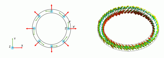
The directions of X, Y, and Z axis of the material are assumed to be positioned as shown below. X’, Y’, and Z’ in the diagram correspond to the directions of X, Y, and Z of the material.
Body Attributes and Materials
|
Body Number/Type |
Body Attribute Name |
Material Name |
|
0/Solid |
Body_Attribute_Name_001 |
202_Lithium_niobate |
* Available from the material DB
|
Body Attribute Name |
Tab |
Setting |
||||||||||||||||||||||||||||||||||
|
Body_Attribute_Name_001 |
Direction |
Specified by: Vector Enter two vectors and specify 3 directions is selected Select Use distribution data |
||||||||||||||||||||||||||||||||||
|
Use Z’ vector distribution Edit Distribution Data dialog box Distribution Dimension: 2D Coordinate System: Global Coordinates
|
||||||||||||||||||||||||||||||||||||
|
Use X’ vector distribution Edit Distribution Data dialog box Distribution Dimension: 2D Coordinate System: Global Coordinates
|
Boundary Condition
|
Boundary Condition Name/Topology |
Tab |
Boundary Condition Type |
Setting |
|
V0/Face |
Electric |
Electric Wall |
Voltage specified: Voltage 0[V] |
|
V1/Face |
Electric |
Electric Wall |
Voltage specified: Voltage 1[V] |
Results
Direction distribution is examined as follows.
Go to Results tab > Display > Solver > Mesh.
Set the field type to Directional distribution. By pressing the Element Vector button, the direction specified by Use Z’ vector distribution is displayed. (Fig (a) below)
Confirm that the result is as intended.
Set the field type to Directional distribution 2. By pressing the Element Vector button, the direction specified by Use X’ vector distribution is displayed. (Fig (b) below)
The displacement in the piezoelectric analysis is examined as follows. Go to Results tab > Display > Solver > Piezoelectric analysis.
By selecting displacement and vectors X, Y, and Z, the element vector diagram is drawn as in Fig (c). Fig (d) is an XZ cross sectional diagram.
Fig (e) is an XY cross sectional diagram.
Reference: Comparison with an axisymmetric analysis
The axisymmetric model is analyzed. The similar results are acquired as the 3D model.
The axisymmetric model is model [AX] included in the attached project.

