
CAE Software【Femtet】Murata Software Co., Ltd.

Example29 Examine the Coriolis Force
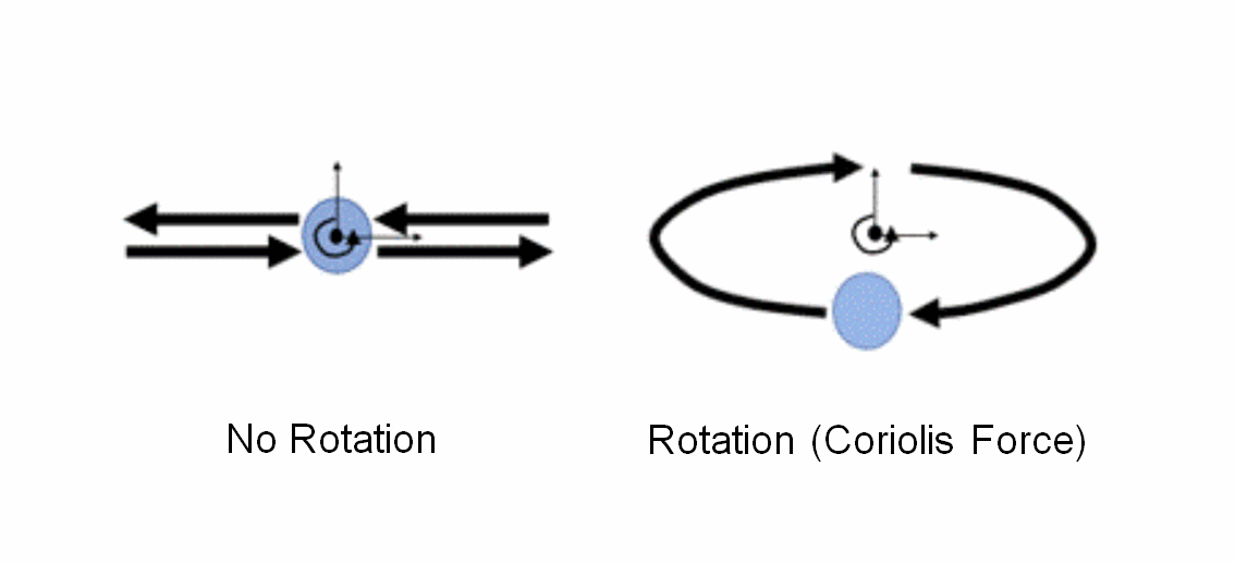
General
-
A theoretical value and calculated value of the Coriolis force are compared.
-
The analysis is without piezoelectricity.
Analysis Condition
|
Item |
Setting |
|
Solver |
Piezoelectric analysis [Galileo] |
|
Analysis Space |
3D |
|
Analysis Type |
Harmonic Analysis |
|
Unit |
mm |
|
Variables to Constrain |
Select Electric Potential |
|
Analysis Options |
Select Acceleration Select Angular Velocity for the model: rotation Deselect Angular Velocity for the model: no_rotation |
The Acceleration tab is set as shown below.
|
Tab |
Setting Item |
Setting |
|
Acceleration |
Acceleration |
X=Z=0.0, Y=2.e5[m/s2] |
|
Angular Velocity(*) |
Angular Velocity |
X=Y=0.0, Z=1000[rad/s] |
(*)This setting is for the rotation model only.
Model
A spherical solid body is defined.

Body Attributes and Materials
|
Body Number/Type |
Body Attribute Name |
Material Name |
|
0/Solid |
Body_Attribute_001 |
008_Cu (*) |
* Available from the material DB
Boundary Condition
None
Results
The deformation diagrams of the result fields are shown below.
The diagrams are drawn with an actual scale. See Displacement diagram for the scale setting.
The dotted lines are the trajectory of the sphere. They are added for easy viewing. They are not drawn by Femtet.

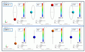
Fig 1. Contour diagram (displacement/magnitude) + displacement (actual scale)
First, let’s look at the model without rotation. The vibration in the Y direction is given by the acceleration of Y component.
It is confirmed in the lower diagram of Fig 1. The temporal change of the Y component of the displacement is shown in Fig 2.
The phases are on the horizontal axis. The phase of 360 [deg] represents one period.
Since analysis is executed with 1 [KHz], 360 [deg] is 1 [ms]. The displacement of the center of the spheric body is plotted on the graph.
From Fig 2, it can be read that the marker M02 of the maximum point of the no_rotation model is 5.066 [mm].
This matches with a theoretical value of 5.066 [mm] given by the formula in the appendix below.
Next, let’s look at the model with rotation. The displacement in the X direction is generated as well due to the Coriolis force.
As in the upper diagram of Fig 1, the trajectory is elliptical. The displacement amplitude can be read from the markers in Fig 2 (Y component) and Fig 3 (X component).
Y component: 5.637 [mm]
X component: 1.794 [mm]
They match with the theoretical values in the appendix below.

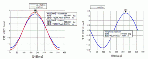
Fig 2 Temporal change of the Y component of the displacement Fig 3 Temporal change of the X component of the displacement
Appendix: Theoretical Calculation
[Without Rotation]

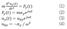
From the entered values for analysis, the following are given.
Y component of acceleration: αy = 2.e5[m/s2]
Angular frequency: ω = 2π1000[rad/s](driving frequency 1[KHz])
From the above two and equation (4), the Y component of the displacement is obtained as below.
u0y=-5.066e-3[m]
[With Rotation]
The equation (5) is a motion equation including the Coriolis force.


Since the entered value of the angular velocity is Z component only, the equation is written as (6)
By substituting the equations (6), (7), and (8) in the equation (5), the following equations are given.

![]()
The X and Y components of the displacement are gained as below.

![]()
Angular velocity of rotation: Ωz=1000[rad/s]
X component of displacement: u0x= j 1.794e-3[m]
Y component of displacement: u0y= -5.637e-3[m]

