
CAE Software【Femtet】Murata Software Co., Ltd.

Example18 Restart under Different Boundary Condition
General
-
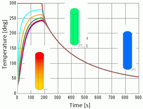
The transient analysis is restarted after the boundary condition is changed from “temperature” to “heat transfer/ambient radiation”.
-
The temperature distribution and the heat flux vectors are solved.
-
Unless specified in the list below, the default conditions will be applied.
Analysis Space
|
Item |
Settings |
|
Analysis Space |
3D |
|
Model unit |
mm |
Analysis Conditions
|
Item |
Settings |
|
Solver |
Thermal Analysis [Watt] |
|
Analysis Type |
Transient analysis |
|
Options |
N/A |
The Transient Analysis tab is set up as follows. The initial temperature is 25[deg] and the time step is 10[sec].
The calculation steps are 18 and 72 before and after restart respectively..
Initial Setting:
|
Tab |
Setting Item |
Settings |
||||||||
|
Transient analysis |
Table |
|
||||||||
|
Restart |
Deselect “Continue from the last session” |
|||||||||
|
Initial Temperature |
25[deg] |
The settings for the restart
|
Tab |
Setting Item |
Settings |
||||||||
|
Transient analysis |
Table |
|
||||||||
|
Restart |
Select “Continue from the last session” |
|||||||||
|
Initial Temperature |
N/A |
* After the first leg, change the analysis conditions and boundary conditions. Then start the next leg by clicking Run Mesher/Solver -> Run Solver.
Model
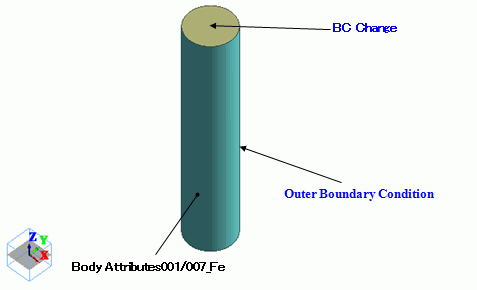
The initial temperature of the cylindrical body is 25[deg]. The top face is set to 300[deg] with the temperature boundary condition.
The boundary condition is changed to the natural convection and the ambient radiation in the next leg.
Body Attributes and Materials
|
Body Number/Type |
Body Attribute Name |
Material Name |
|
0/Solid |
A001 |
007_Fe * |
* Available from the Material DB
Boundary Conditions
Change the boundary condition of BC_Change in the interval between the first and second transient analyses as follows.
|
Boundary Condition Name/Topology |
Tab |
Boundary Condition Type |
Settings |
|
BC_Change/Face (in the first leg) |
Thermal |
Temperature |
300[deg] |
|
BC_Change/Face (in the second leg) |
Thermal |
Heat Transfer/Ambient Radiation |
Select “Natural convection (automatic calculation)”. Also select “Ambient radiation” and set 1.0. Room temperature : 25[deg] |
|
Outer Boundary Condition |
Thermal |
Heat Transfer/Ambient Radiation |
Select “Natural convection (automatic calculation)”. Also select “Ambient radiation” and set 1.0. Room temperature : 25[deg] |
Results
Diagram below shows the temperature distribution at 90[s].
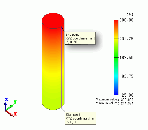
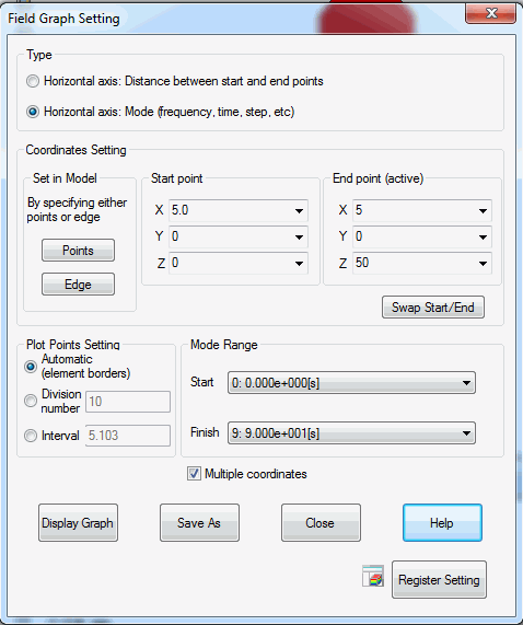
The temperatures of 5 points in the model will be drawn through the following chart setting. The 5 points for the chart are set at regular intervals form the bottom to the top.
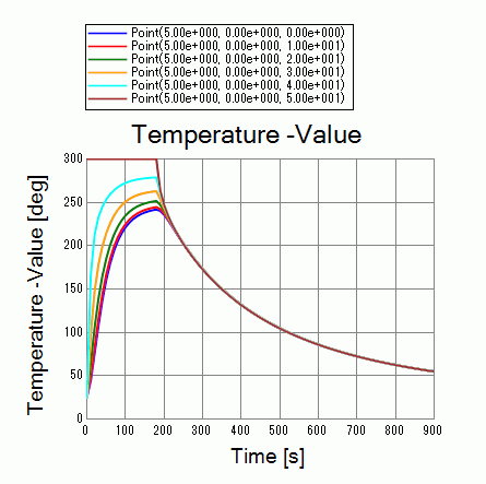
The temperatures increase for the first 180 seconds. But after the boundary condition on the top face is changed, they decrease.

