CAE Software【Femtet】Murata Software Co., Ltd.

Example8 Mechanical Stress Analysis of Operating IC after Soldering
General
-
This is the modified exercise of Exercise 10: Multi-Step Thermal Load Analysis for IC Soldering Process.
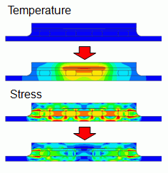
The analysis is set with time. The mechanical stress analysis with temperature distribution is performed on the IC which is operating after soldered on the substrate.
-
By setting time, elasto-plasticity and creep of solder can be taken into account.
-
By setting [multi-step thermal load + Thermal coupled steps], the thermal analysis solves the temperature of the operating IC.
The distributed mechanical stress is calculated with the obtained temperature. -
The distributions of the deformation, displacement and the mechanical stress are solved for each temperature.
-
Unless specified in the list below, the default conditions will be applied.
Analysis Space
|
Item |
Setting |
|
Analysis Space |
2D |
|
Model unit |
mm |
Analysis Conditions
To simplify the analysis, the 2-D model is analyzed.
Select the thermal load option.
|
Item |
Settings |
|
Solvers |
Thermal Analysis [Watt] |
|
Thermal-Analysis Type |
Transient Analysis |
The process is as follows.
Step 1 The IC is soldered on the substrate at 220[deg] and cooled down to 25[deg].
Step 2 The temperature is increased from 25[deg] to 120[deg].
Step 3 At 120[deg], the underfill is applied and hardened. After the hardening, the temperature is decreased to 25[deg].
Step 4 The IC is activated and will generate the heat.
The multi-step thermal load analysis of the mechanical stress analysis is used through the Step 3.
At the Step 4, the transient analysis of the thermal analysis and the coupled analysis function of the mechanical stress analysis are used.
The Thermal Load tab is set as follows.
|
Tabs |
Setting Item |
Setting |
|
Thermal Load |
Reference temperature |
220[deg] |
|
Setting |
Select “Continue from the last session” |
The reference temperature (non-stress temperature) is 220[deg] The reached temperature is set on the step analysis tab.
The Step/Thermal Load tab is set as follows.
|
Tab |
Setting Item |
Setting |
|||||||||||||||
|
Step/Thermal load |
Step Setting |
Multi-step thermal load + thermal coupled steps |
|||||||||||||||
|
Time Setting |
Set up * |
||||||||||||||||
|
Reference temperature |
220[deg] |
||||||||||||||||
|
Step/Reached Temperature Setting |
|
||||||||||||||||
|
Options for the Multi-Step Analysis |
Save the results of substeps : Deselect |
* If the analysis is coupled with transient analysis, [Set up] is automatically selected.
* Thermal coupled steps are set up on the transient analysis tab.
The transient analysis tab is set as follows.
Normally, the initial temperature is set for the thermal transient analysis. The reached temperature in the step analysis will be used as the initial temperature.
It is set at 25[deg].
|
Tab |
Setting Item |
|
Transient Analysis |
Calculation Step: 5 |
The underfills are subjected to the analysis on and after Step 3. Therefore, the setting is done on the Analysis Domain tab of the Body Attribute.
Graphical Objects
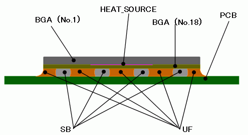
Body Attributes and Materials
|
Body Number/Type |
Body Attribute Name |
Material Name |
|
0/Sheet |
PCB |
GLASS_EPOXY |
|
1/Sheet |
BGA |
EPOXY |
|
3/Sheet |
SB |
107_Lead-free_solder_SnAgCu |
|
4/Sheet |
SB |
107_Lead-free_solder_SnAgCu |
|
5/Sheet |
SB |
107_Lead-free_solder_SnAgCu |
|
6/Sheet |
SB |
107_Lead-free_solder_SnAgCu |
|
11/Sheet |
UF |
UNDER_FILL |
|
12/Sheet |
UF |
UNDER_FILL |
|
13/Sheet |
UF |
UNDER_FILL |
|
14/Sheet |
UF |
UNDER_FILL |
|
15/Sheet |
UF |
UNDER_FILL |
|
17/Sheet |
HEAT_SOURCE |
GLASS_EPOXY |
|
18/Sheet |
BGA |
GLASS_EPOXY |
* Available from the Material DB
The material properties are set up as follows:
|
Material Name |
Tab |
Properties |
|||||
|
GLASS_EPOXY |
Elasticity |
Young’s modulus: 28×10^9[Pa] Poisson’s ratio: 0.3
|
|||||
|
Coefficient of Expansion |
Anisotropy: Select Anisotropic. Vector of expansion coefficient
|
||||||
|
Thermal Conductivity |
0.45[W/m/deg] |
||||||
|
Density |
1.44 x 10^3 [kg/m3] |
||||||
|
Specific Heat |
950 [J/kg/deg] |
||||||
|
EPOXY |
Elasticity |
Young’s modulus: 19×10^9[Pa] Poisson’s ratio: 0.3 |
|||||
|
Coefficient of Expansion |
11×10^-6[1/deg] |
||||||
|
Thermal Conductivity |
0.15[W/m/deg] |
||||||
|
Density |
1.1 x 10^3 [kg/m3] |
||||||
|
Specific Heat |
1.05 x 10^3 [J/kg/deg] |
||||||
|
UNDER_FILL |
Elasticity |
Young’s modulus: 3.5×10^9[Pa] Poisson’s ratio: 0.3 |
|||||
|
Coefficient of Expansion |
90×10^-6[1/deg] |
||||||
|
Thermal Conductivity |
0.15 |
||||||
|
Density |
1.1 x 10^3 [kg/m3] |
||||||
|
Specific Heat |
1.05 x 10^3 [J/kg/deg] |
UF is set up as follows.
The thermal coupled analysis will be performed in the Step 3. The state of the Step 3 will be reflected from Step 3 onward.
As a heating place, HEAT_SOURCE is set on the Heat Source tab as follows.
|
Body Attribute Name |
Tab |
Setting |
|
UF |
Analysis Domain |
Birth/Death Setting: Step 1: No |
|
HEAT_SOURCE |
Heat Source |
5 x 10^-4[W] |
Boundary Conditions
Select “Natural convection (automatic calculation)” on the outer boundary condition.
|
Boundary Condition Name/Topology |
Tab |
Boundary Condition Type |
Setting |
|
Outer Boundary Condition |
Heat |
Heat Transfer/Ambient Radiation |
Natural convection (automatic calculation) Room temperature: 25[deg] |
* The correction coefficient for the natural convection is calculated automatically. See [Heat Transfer/Ambient Radiation] for more information.
Results
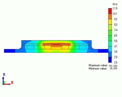
The temperature distribution 100s after the analysis is shown below.
Temperature rise is observed around HEAT_SOURCE.
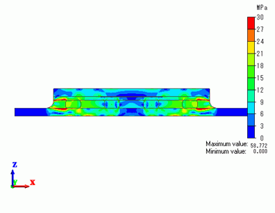
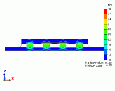
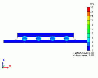
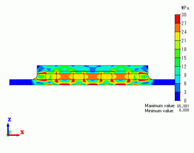
The distribution of the von Mises equivalent stress for each step in the analysis is shown below.
The scale of the stress is minimum: 0[MPa] and maximum: 30[MPa].
Step 1: 220℃⇒25℃: 100s
Step 2: 25℃⇒120℃: 200s
Step 3: 120℃⇒25℃: 300s
Step 4: 25℃⇒Thermal conductivity 100s later: 400s
