CAE Software【Femtet】Murata Software Co., Ltd.

Example2 Heat Radiation of Plate (Turbulent Flow) by Forced Convection

General
-
Heat dissipation of a flat plate by the forced convection is solved by the steady-state analysis.
-
The temperature distribution and the heat flux vectors are solved.
-
Unless specified in the list below, the default conditions will be applied.
-
Obtain this session's project file. (Save the project file before open)
Two analysis models with different mesh settings are included in a project. (turbulent, turbulent_mesh)
Analysis Space
|
Item |
Setting |
|
Analysis Space |
2D
Thickness in depth direction: 300mm |
|
Model Unit |
mm |
Show Results
|
Item |
Setting |
|
Solver |
Fluid Analysis [Bernoulli] Thermal analysis [Watt] |
|
Analysis Type |
Steady-State Analysis |
|
Laminar Flow/Turbulent Flow |
Select Laminar Flow |
|
Meshing Setup |
General Mesh size: 10[mm] |
Model
The material of Air (000_Air) is set to a rectangular sheet body. The boundary conditions of inlet and outlet are set on the left edge and the right edge respectively.
A heat source of thin flat plate is defined by the rectangle sheet body.
The slip wall outer boundary condition is applied to the top and bottom edges where the boundary condition is not set.
Body Attributes and Materials
|
Body Number/Type |
Body Attribute Name |
Material Name |
|
0/Solid |
air |
000_Air(*) |
|
1/Solid |
hot |
hot |
* Available from the material DB
The material properties of the thin flat plate are set as follows.
|
Material Name |
Tab |
Properties |
|
hot |
Solid/Fluid |
Solid |
|
Thermal conductivity |
1x 10*5 |
The heat source of the thin flat plate is set on the heat source tab as follows.
|
Body Attribute Name |
Tab |
Setting |
|
hot |
Heat source |
100W |
Boundary Condition
|
Boundary Condition Name/Topology |
Tab |
Boundary Condition Type |
Setting |
|
Inlet/Edge |
Thermal Fluid |
Inlet |
Forced Inflow Inflow Temperature : 0[deg] |
|
Outlet/Face |
Thermal Fluid |
Outlet |
Natural Outflow |
|
Outer Boundary Condition |
Thermal Fluid |
Slip wall |
– |
It is said that the flow over the flat plate transitions to the turbulent flow at the Reynolds number of around 5×10^5
The Reynolds number calculated from this model form, material property, and fluid velocity is about 198600. It is close to the Reynolds number where the laminar flow transitions to turbulent flow. The turbulent flow is analyzed.
Viscosity μ=1.82e-5[Pa s]
Density ρ=1.205[kg/m3]
Kinematic viscosity v=μ/ρ=1.82e-5/1.205=1.510e-5[m2/s]
Fluid velocity V=10[m/s]
Length of plate L=0.3[m]
Reynolds number Re = V*L/ν=10*0.3/1.510e-5 = 198600
Results
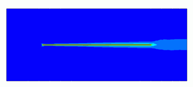
The temperature distribution is shown below.
The maximum temperature is 15.720 [deg].
Below is the plotting of the temperature distribution from coordinates (250,0,-100) to coordinates (250,0,100).
A boundary layer of about 10mm is created.
The results of the turbulent thermal conductivity is shown below.
The thermal conductivity around the wall surface becomes large.
It indicates that the thermal diffusion is active due to the turbulent flow.
y+[%] and the height of the 1st layer mesh [mm] are shown to examine the mesh state.
More than 90[%] exist between y+=30 and y+=200.
It can be said that the setting is proper for the analysis using the wall function.
By calculating the domain accurately, where y+ is small (closer to the wall), the accuracy can be improved.
Set the layer mesh referring to the recommended height of 1st layer mesh [um].
In this example, set the recommended value of 0.127[mm] for y+<5 to perform analysis again.
By setting the growth rate of 1.2 and the number of layers of 12, total height becomes y+=200 if the 1st layer is y+=5. This setting can handle the domain where the change is large.
|
Item |
Setting |
|
Layer Mesh Setting for Wall Surface (General Settings) |
Select Specify mesh height of 1st layer Height of 1st layer mesh: 0.127 [mm] Growth rate: 1.2 The number of layers: 12 |
|
Analysis type |
Steady-State Analysis |
|
Laminar Flow/Turbulent Flow |
Select Laminar Flow |
|
Meshing Setup |
General Mesh size: 10[mm] |
The temperature distribution with new mesh setting is shown below.
The maximum temperature is 11.129 [deg].
The result is close to a theoretical value of 11.10[deg].
<Theoretical Value Calculation>
Heat source Q=100 [W]
Thickness of plate W=0.3 [m]
Length of plate L=0.3 [m]
Average heat flux q=Q/(2*L*W)=556 [W/m2]
Viscosity μ=1.82e-5[Pa s]
Density ρ=1.205[kg/m3]
Kinematic viscosity v=μ/ρ=1.82e-5/1.205=1.510e-5[m2/s]
Thermal conductivity λ=0.0265[W/m/deg]
Specific heat Cp=1006[J/Kg/deg]
Temperature diffusivity α = λ/(ρ*Cp) = 2.19e-5 [m2/s]
Prandtl number Pr = ν/α = 0.691
Fluid velocity V=10[m/s]
Turbulent average heat transfer h = 0.037 λPr^1/3 ν^(-4/5) V^(4/5) L^(-1/5) = 50.03 [W/m2/deg]
Temperature difference ΔT = q/h = 11.10[deg]

