CAE Software【Femtet】Murata Software Co., Ltd.

Example3 Heat Radiation of IC by Forced Convection

General
-
Heat dissipation of an IC on the substrate by the forced convection is solved by the steady-state analysis.
-
The temperature distribution and the heat flux vectors are solved.
-
Unless specified in the list below, the default conditions will be applied.
-
Obtain this session's project file. (Save the project file before open)
Analysis Space
|
Item |
Setting |
|
Analysis Space |
3D |
|
Model Unit |
mm |
Show Results
|
Item |
Setting |
|
Solver |
Fluid Analysis [Bernoulli] Thermal analysis [Watt] |
|
Analysis Type |
Steady-State Analysis |
|
Laminar Flow/Turbulent Flow |
Select Turbulent Flow |
|
Meshing Setup |
General Mesh size: 5 [mm] |
Model
The model is a box solid body. The material is Air (000_Air). The boundary conditions of inlet and outlet are set on the left edge and the right edge respectively.
The slip wall outer boundary condition is applied to the top and bottom edges where the boundary condition is not set.
The substrate (VOL1) and IC (VOL2) are solid bodies.
Setting of Body Attributes, Materials, and Mesh Sizes
|
Body Number/Type |
Body Attribute Name |
Material Name |
Mesh Size |
|
0/Solid |
VOL1 |
006_Glass_epoxy * |
0.2 |
|
1/Solid |
VOL2 |
001_Alumina * |
0.2 |
|
2/Solid |
Air |
000_Air(*) |
– |
* Available from the material DB
IC (VOL2) is set as follows on the Heat source tab.
|
Body Attribute Name |
Tab |
Setting |
|
VOL2 |
Heat Source |
1W |
Boundary Condition
|
Boundary Condition Name/Topology |
Tab |
Boundary Condition Type |
Setting |
|
In/Edge |
Thermal Fluid |
Inlet |
Forced Inflow Inflow Temperature : 25[deg] |
|
Out/Face |
Thermal Fluid |
Outlet |
Natural Outflow |
|
Outer Boundary Condition |
Thermal Fluid |
Slip wall |
– |
Results
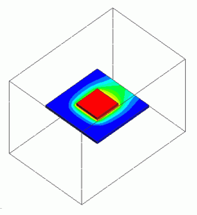
The temperature distribution is shown below.
For easy viewing of the temperature distributions of the substrate and the IC, the ambient air field is hidden by right-clicking the air body and selecting [Hide Body Field].
As the upstream side is more likely to get cooler, the temperature distribution is biased. The temperature on the downstream side of the substrate surface is higher than the upstream side.

